This thread has been locked.

If you have a related question, please click the "Ask a related question" button in the top right corner. The newly created question will be automatically linked to this question.

DS90UB948-Q1: Why does my DS90UB948 enter auto-scroll mode automatically after the device is powered on?

Part Number: DS90UB948-Q1
Other Parts Discussed in Thread: ALP

Tool/software:

Dear TI,

I am working with the DS90UB949A connected to a DS90UB948, which in turn is connected to an LCD display.

The DS90UB949A and DS90UB948 are on separate boards, linked by a cable transmitting LVDS signals and power. We've observed that after powering on the DS90UB948 (with the LCD attached), the LCD automatically scrolls through white, red, green, and other color patterns repeatedly.

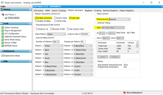
We have not yet configured the DS90UB948. Even when we disconnect the LVDS cable, the issue persists. We attempted to modify registers 0x64 and 0x65 of the DS90UB948 via the I2C interface of the DS90UB949A. Although the register values changed, the output to the LCD did not.

I noticed that controlling the pattern generator (PATGEN) via the serializer is not supported (as mentioned in the document SNLA132G). I2C is not utilized in the local configuration of the DS90UB948 on our board. How can we resolve this issue if the local I2C of the DS90UB948 is not an option for us?

  • Hi Yan,

    We have not yet configured the DS90UB948.

    If you have not configured the SerDES, your patgen is likely coming from the display. This is not related to the SERDES. 

    Does you LCD display have a TCON or some internal MCU that supports patgen?

    I noticed that controlling the pattern generator (PATGEN) via the serializer is not supported

    This is a supported feature. You should be able to send patgen from 949 or 948. 

    Are you using ALP to control SERDES or how are you talking to I2C of the SERDES?

    Even when we disconnect the LVDS cable

    When you say LVDS cable are you refering to FPD-Link Cable between Ser and Des or is that the cable between 948 and LCD display? 

    Can you send me a register dump of this issue?

    Do you have a reg dump of a good run vs bad run ?

    Regards,
    Fadi A.

  • Hi Fadi,

    Thank you for your prompt reply. We have observed various patterns on our LCD output.

    I have a few additional questions:

    1. After disabling the LCD pattern and enabling the 948 PATGEN (via the local I2C of 948), I can measure the output clock at 33 MHz, but there are no data waves detected. What could be the issue? [Reference setting: Section 4.1 of snla132g.pdf]

    2. I've noticed that when I enable the BIST of 948 by writing to the 948 register (not using the pin), I can no longer access the 948 registers via the 949 I2C. Is this due to the use of an internal clock or another reason?

    3. If my HDMI input video is 720p, should I adjust some registers on the 948 and 949? I've found that the 949 pattern requires setting timing and resolution, but I cannot find the relevant registers for this purpose in the 948 and 949.

  • Hi Yan,

    After disabling the LCD pattern and enabling the 948 PATGEN (via the local I2C of 948), I can measure the output clock at 33 MHz, but there are no data waves detected. What could be the issue? [Reference setting: Section 4.1 of snla132g.pdf]

    Are you enabling the patgen block? If you are using ALP you can enable it by toggling the following boxes:

    1. Enable generator 
    2. Enable color bars
    3. timing source: Internal timing 
    4. Spec 720P 60Hz


    I've noticed that when I enable the BIST of 948 by writing to the 948 register (not using the pin), I can no longer access the 948 registers via the 949 I2C. Is this due to the use of an internal clock or another reason?

    BIST mode will send a high speed pattern which will take over the entire link so you won't be able to use remote I2C. 

    If my HDMI input video is 720p, should I adjust some registers on the 948 and 949? I've found that the 949 pattern requires setting timing and resolution, but I cannot find the relevant registers for this purpose in the 948 and 949.

    Here is the script for 720p from 949

    import time
    #TH = 1648
    #AH = 1280
    #TV = 750
    #AV = 720
    #HBP = 216
    #HFP = 72
    #HS = 80
    #VBP = 22
    #VFP = 3
    #VS = 5
    
    Ser_addr = 0x18
    
    time.sleep(0.5)
    board.WriteI2C(Ser_addr,0x01,0x02) # Reset
    
    board.WriteI2C(Ser_addr,0x3,0xDA) #Passthrough I2C
    
    time.sleep(0.5)
    board.WriteI2C(Ser_addr,0x5B,0x00) #Auto-detect 
    
    board.WriteI2C(Ser_addr,0x1E,0x01) #Select FPD-Link III Port 0
    board.WriteI2C(Ser_addr,0x66,0x1A)
    board.WriteI2C(Ser_addr,0x67,0x01) #M=1
    board.WriteI2C(Ser_addr,0x66,0x03)
    board.WriteI2C(Ser_addr,0x67,0x03) #N=3
    
    board.WriteI2C(Ser_addr,0x66,0x04)
    board.WriteI2C(Ser_addr,0x67,0x70) #least 8 bit of Total Horizontal frame size
    board.WriteI2C(Ser_addr,0x66,0x05)
    board.WriteI2C(Ser_addr,0x67,0xE6) #Least 4 bit TV + Most 4 bit TH
    board.WriteI2C(Ser_addr,0x66,0x06)
    board.WriteI2C(Ser_addr,0x67,0x2e) #Most 8 bit of Total Vertical frame size
    
    board.WriteI2C(Ser_addr,0x66,0x07)
    board.WriteI2C(Ser_addr,0x67,0x00) #least 8 bit of active Horizontal frame size
    board.WriteI2C(Ser_addr,0x66,0x08)
    board.WriteI2C(Ser_addr,0x67,0x05) #Least 4 bit AV + Most 4 bit AH
    board.WriteI2C(Ser_addr,0x66,0x09)
    board.WriteI2C(Ser_addr,0x67,0x2d) #Most 8 bit of active Vertical frame size
    
    board.WriteI2C(Ser_addr,0x66,0x0A)
    board.WriteI2C(Ser_addr,0x67,0x50) #Horizontal Sync Width
    board.WriteI2C(Ser_addr,0x66,0x0B)
    board.WriteI2C(Ser_addr,0x67,0x05) #Vertical Sync Width
    board.WriteI2C(Ser_addr,0x66,0x0C)
    board.WriteI2C(Ser_addr,0x67,0xD8) #Horizontal back porch
    board.WriteI2C(Ser_addr,0x66,0x0D)
    board.WriteI2C(Ser_addr,0x67,0x16) #Vertical back porch
    
    board.WriteI2C(Ser_addr,0x65,0x04) #using internal timing and internal clock
    board.WriteI2C(Ser_addr,0x64,0x15) #enable PG/color bars
    
    
    board.WriteI2C(Ser_addr,0x1E,0x01) #Select FPD-Link III Port 0
    board.WriteI2C(Ser_addr,0x07,0x58) #remote Deserializer ID
    board.WriteI2C(Ser_addr,0x08,0x5C) #remote Deserializer alias
    board.WriteI2C(Ser_addr,0x03,0xDA) #Enable I2C_PASSTHROUGH, FPD-Link III Port 0
    

    Regards,
    Fadi A.