This thread has been locked.

If you have a related question, please click the "Ask a related question" button in the top right corner. The newly created question will be automatically linked to this question.

DP83867IR: Drop-in replacement

Part Number: DP83867IR

Tool/software:

Hi,

One question on LED_0 strap option. When I set it to mode 3, does that mean ports are mirrored internally or port mirror feature is enabled? 

My hardware is able to connect to PC only in mode 3 but not in mode 1 (with no change in rest of the hardware/software). I have not swapped the ports in my PCB.

Best regards,

Bhagavath

  • Hi Bhagavath,

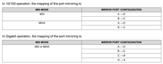
    Mirror mode remaps the PHY channel ports internally:

    In this case, it seems mirror mode is required as there is some port crossing occurring, either on the board traces / cable / RJ-45 connector.

    Thank you,

    Evan

  • Magjack.pdf6472.ETHERNET Schematics.pdf

    Thanks Evan for the quick response.

    I have attached my schematics & connector diagram & you can see that they are one to one. I have checked my cable also & the connection is one to one.

    Board is working only when strap resistors for LED_0 pin are mounted.

  • Hi Bhagavath,

    Thanks for sharing schematics, I agree that the connection does not seem crossed and should work without mirror mode.

    Could you please share register readouts for address 0x11 and 0x31 in the working and failing cases so I can confirm the strap setting is being set as intended?

    Thank you,

    Evan

  • Dear Evan,

    Below are the register read values.

    With pull up/down on LED_0 (pin 47):

    X11: BC3E
    X31: AC3E
    X6E: 8005
    X6F: 0100
    Without pull up/down on LED_0 (pin 47):
    X11: 0302
    X31: 0302
    X6E: 0005
    X6F: 0100
    Thanks & best regards,
    Bhagavath
  • Hi Bhagavath,

    Thanks for sharing the registers. Register 0x11 = 0xBC3E indicates that the PHY detects reversed channel polarity on the channels due to wire crossing.

    Reviewing the schematic and magjack diagram again, I don't see any wire crossing. Can you please share the layout file so I can review if the symbol was potentially inverted or crossed in some way?

    Thank you,

    Evan

  • Thanks Evan.

    I need to check with my customer regarding sharing the layout file. Can you please send your email ID where I can share the brd file.

    I saw some threads which say that DM83867 has week driver with 1.8V IO supply. Is this true? Some people said that when they increased the supply to 2.5V, RGMII read issue got resolved. I don't have any option to change the IO voltage from 1.8V.

    One observation from the read register values is, we are setting 0000 as PHY address through strap resistors but the read value 0101. I am not sure if the driver over-rights the value during configuration process. My software engineer is saying, he is getting few other values also when he read the register.

    Meanwhile, we are checking if any RGMII loopback test code is available.

    Best regards,

    Bhagavath

  • Hi Bhagavath,

    Please send layout to e-mayhew@ti.com

    Could you share more details about the strap register reads? I assume this is register 0x6E for PHY address, does your colleague see the value change over multiple reads?

    After sharing this, I can confirm if this is due to 1.8V IO driver or another cause.

    It's possible the strapped configuration is overridden due to processor driving the line and affecting the voltage seen at the PHY pin during startup, but this value should remain static after the straps latch.

    Please confirm register read/write sequence is following this FAQ for extended registers:

    https://e2e.ti.com/support/interface-group/interface/f/interface-forum/1271487/faq-extended-register-space-access-for-ethernet-phys

    "Read / Write (No Post Increment) Operation"

    Thank you,

    Evan

  • Thanks Mr. Evan,

    Do you want us to read 0x6E repeatedly & check if the data changes? Or with multiple power ON/OFF conditions?

    Regarding mirror enable, you are correct. Ports A & D and ports B & C are swapped in the connector because of wrong pin assignment in the connector footprint. In the connector footprint, pins 1-6 are mirrored, similarly pins 7-12 are mirrored. Surprisingly & thankfully this error exactly matches with the ports mirror feature of DP83867.

    Is there any known issue between Zynq7000 FPGA & DP83867 with 1.8V IO voltage? I have connected DP83867 to Zynq Ultrascale+ in other project & that is working fine. With Zynq7000, MII loopback (setting bit 14 to high of BMCR 0x0000 register) is failing.

    One more question is about setting the clock skew. In Ultrascale+ board, default skew setting (2ns) for both Tx & Rx clock is working. In Zynq7000 board, we tried few skew options but no success.

    I will be asking few questions everyday this week, hope you won't mind.

    Best regards,

    Bhagavath

  • Hi Bhagavath,

    One observation from the read register values is, we are setting 0000 as PHY address through strap resistors but the read value 0101. I am not sure if the driver over-rights the value during configuration process. My software engineer is saying, he is getting few other values also when he read the register.

    Are you seeing different values while re-reading the register over one power cycle, or only different values over multiple power cycles? I am interested in any case that yields different values for 0x6E, as this register should have a static configuration.

    Ports A & D and ports B & C are swapped in the connector because of wrong pin assignment in the connector footprint.

    Glad we found the cause here, and thankful that the accidental pinmapping is acceptable for mirror mode.

    Is there any known issue between Zynq7000 FPGA & DP83867 with 1.8V IO voltage? I have connected DP83867 to Zynq Ultrascale+ in other project & that is working fine. With Zynq7000, MII loopback (setting bit 14 to high of BMCR 0x0000 register) is failing.

    There are no known issues here. If 1.8VDDIO is being used, MDC/MDIO are on this voltage domain, and the MDC/MDIO transactions are valid, I don't expect any issues with register reads/writes. Is it specifically just 0x0[14] that is failing to change, where other bits can be modified and read back accurately?

    One more question is about setting the clock skew. In Ultrascale+ board, default skew setting (2ns) for both Tx & Rx clock is working. In Zynq7000 board, we tried few skew options but no success.

    This depends heavily on delays due to trace length and layout. If you can probe the MAC lines and read the delay between clock and data, you may be able to converge on the correct delay setting more quickly. Otherwise, I recommend iterating delay settings until valid packets are seen between MAC<->PHY. 

    Thank you,

    Evan

  • Thanks Mr. Evan for the detailed response.

    Regarding PHY address, there were some default pull ups in Zynq7000 on RXD lines which was changing the PHY address. When those pull ups were disabled, we are consistently getting 0 as PHY address (as per our strap setting).

    Regarding MII loopback, we have no problem in setting 0x0[14], but loopback test is failing. MDC/MDIO is working perfectly for us.

    For us RGMII interface is failing. We are able to auto negotiate & link up is happening at all 10/100/1000 speeds. I believe RGMII interface will not be used during auto-negotiation process, it will be through MDC/MDIO. I need to do some study on this.

    Best regards,

    Bhagavath

  • Hi Bhagavath,

    Is communication failing at Gigabit speed?

    RGMII timing requirements are strict in 1000M, so register tuning with addresses 0x32 and 0x86 is typically required.

    I recommend the following test cases:

    - 0x32[1:0] = '00' (TX/RX align mode)

    - 0x32[1:0] = '11' (TX/RX shift mode)

    - 0x86[7:0] = 0xFF (TX/RX delay = 4ns in shift mode)

    - 0x86[7:0] = 0x33 (TX/RX delay = 1ns in shift mode)

    As these timing requirements are easier to meet for 10/100M speeds, testing with lower link speed is another way to confirm delay setting as the root cause.

    Thank you,

    Evan

  • Dear Mr. Evan,

    We are trying at 10 MBPS speed. Will try the above settings tomorrow.

    Thanks

    Bhagavath

  • Hi Bhagavath,

    Sounds good, please share updates when able.

    Thank you,

    Evan