This thread has been locked.

If you have a related question, please click the "Ask a related question" button in the top right corner. The newly created question will be automatically linked to this question.

DS90UB954-Q1: DS90UB960-Q1 to DS90UB953-Q1 to DS90UB954-Q1 to ??? I2C

Part Number: DS90UB954-Q1


Tool/software:

Hello


After asking a previous question about a proposed system, I now have it physically setup and require further assistance relating to the I2C passthrough.

I had the following response related to passing the I2C data between camera and display:

This line up should be compatible. If the camera is able to lock onto and function properly with the 960 in the original system, then the camera should be compatible with a 954 as well. If you have the original system available you may be able to determine which serializer is being used by the camera via the device's registers. There are ID registers that can be read to determine the device, for example see registers 0xF0 - 0xF5 on the 953. 

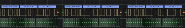
I can see that the 960 is able to communicate and setup registers on the 953 (I can see the GPIO setup registers change value when the 960 is connected to it), but I assume that back channel setup data is intended for the camera? I do not know the address of the camera and I cannot access it's I2C lines as it is encapsulated. I have observed that the 960 is sending out I2C writes, over the back channel, to addresses 0x10, 0x08 and 0x50.

My 953 has address 0x18 and my 954 has address 0x34. What registers do I need to setup to get the I2C commands from the display to the camera? 

I know I need to setup passthrough and update the IDs, but beyond that I'm a little unsure.

Many Thanks
Dan

  • Hello Dan,

    Yes, you can access the image sensor using the pass throu mode. Let’s assume 960+953 is link A and 954+ Cam SER is link B and Imager is 0x20:

    SoC --> 960 (A) --> 953 (A) --> 954 (B) --> Cam SER (B) --> Imager.
     
     
    Program 960 (A):
    0x58[6]=1 for Pass-throu enabled
    0x5D: SlaveID[0] = 0x20
    0x65: SlaveAlias[0] = 0x20
     
    Program 954 (B):
    0x58[6]=1 for Pass-throu enabled
    0x5D: SlaveID[0] = 0x20
    0x65: SlaveAlias[0] = 0x20
     

    In this way you can access the Imager on the camera.

  • Hello Hamzeh

    Thank you for getting back to me. I was able to open up the display unit and access the registers of the 960, to confirm what the SlaveID and SlaveAlias should actually be as I can't change these values. I think the ID and Alias should actually be0x20?

    I've also noticed that 960 (A) is setting register 0x1F to 0x00 (50Mbps back channel), suggesting Cam SER (B) must be a DS90UB953? Would you agree?


    DS90UB960 Register dump with original camera (passed through relays)
         00, 01, 02, 03, 04, 05, 06, 07, 08, 09, 0A, 0B, 0C, 0D, 0E, 0F
    0x00 60, 00, 1C, 40, D0, 01, 00, FF, 9C, 10, 7A, 7A, 6F, 09, 04, 07
    0x10 00, 00, 00, 00, 00, 00, 00, 00, 00, 00, 00, 00, 00, FF, FF, 00
    0x20 C6, 03, 00, 00, 00, 00, 00, 00, 00, 00, 00, 00, 00, 00, 00, 00
    0x30 00, 00, 03, 01, 00, 00, 00, 00, 00, 00, 00, 00, 00, 00, 00, 00
    0x40 00, A9, 71, 01, 00, 00, E0, 00, 00, 00, 00, 12, 12, 43, 45, 64
    0x50 00, 00, 00, 02, 00, 00, 00, 00, 5E, 03, 00, 30, B2, 20, 20, 10
    0x60 A0, 00, 00, 00, 00, 20, 26, 16, A6, 00, 00, 00, 00, 7C, 88, 19
    0x70 6B, 6C, E4, 05, 23, 0B, 40, C5, 00, 01, 00, 00, 00, 00, 00, 00
    0x80 00, 00, 00, 00, 00, 00, 00, 00, 00, 00, 00, 00, 00, 00, 00, 00
    0x90 00, 00, 00, 00, 00, 00, 00, 00, 0A, 5D, 00, 01, FF, FF, 00, 01
    0xA0 00, 00, 00, 00, 00, 1C, 00, 00, 00, 00, 00, 00, 00, 00, 00, 00
    0xB0 1C, 3A, 14, 08, 25, 00, 18, 00, 8C, 33, 83, 74, 00, 00, 00, 00
    0xC0 00, 00, 00, 00, 00, 00, 00, 00, 00, 00, 00, 00, 00, 00, 00, 00
    0xD0 00, 43, 94, 02, 60, F2, 00, 02, 00, 00, 00, 00, 02, 00, 00, 00
    0xE0 00, 00, 00, 00, 00, 00, 00, 00, 00, 00, 00, 00, 00, 00, 00, 00
    0xF0 5F, 55, 42, 39, 36, 30, 00, 00, 00, 00, 00, 00, 00, 00, 00, 00

    I setup 954 (B) with similar settings to 960 (A) (including the ones you suggested above). I can see the 954 (B) Link and Pass LEDs are lit, but not at full brightness, suggesting the link keeps being lost and reestablished?

    I can also see that when 953 (A) sends out I2C commands to 0x20, the clock is stretched for about 100us but there is still no ACK. Writes to the other addresses (0x10 and 0xA0) do not cause this clock stretching. Here is my setup script, we're using our own software and an MCU for writing to the TI Devices, Address highlighted in green, data in red:

    # DS90UB954 Register setup
    #
    #General Configuration (Address 0x02) disable RX parity checker
    c 2 a 0x02 d 0x1C l 1
    #I2C Control 1 (Address 0x08) disable writes to local registers
    c 2 a 0x08 d 0x1C l 1
    #RX_PORT_CTL (Address 0x0C)
    c 2 a 0x0C d 0x81 l 1
    #CSI_PLL_CTL (Address 0x1F)
    c 2 a 0x1F d 0x00 l 1
    #FWD_CTL1 (Address 0x20) port forwarding RX port 0
    c 2 a 0x20 d 0x02 l 1
    #FWD_CTL2 (Address 0x21)
    c 2 a 0x21 d 0x80 l 1
    #CSI_CTL (Address 0x33)
    c 2 a 0x33 d 0x23 l 1
    #FPD3_PORT_SEL (Address 0x4C)
    c 2 a 0x4C d 0x01 l 1
    #BCC_CONFIG (Address 0x58) Enable pass through
    c 2 a 0x58 d 0x5E l 1
    #DATAPATH_CTL1 (Address 0x59) enable GPIO
    c 2 a 0x59 d 0x03 l 1
    #SER_ID (Address 0x5B)
    c 2 a 0x5B d 0x30 l 1
    #SER_ALIAS_ID (Address 0x5C)
    c 2 a 0x5C d 0xB2 l 1
    #TargetID[0] (Address 0x5D)
    c 2 a 0x5D d 0x20 l 1
    #TargetID[1] (Address 0x5E)
    c 2 a 0x5E d 0x20 l 1
    #TargetID[2] (Address 0x5F)
    c 2 a 0x5F d 0x10 l 1
    #TargetID[3] (Address 0x60)
    c 2 a 0x60 d 0xA0 l 1
    #SlaveAlias[0] (Address 0x65)
    c 2 a 0x65 d 0x20 l 1
    #TargetAlias[1] (Address 0x66)
    c 2 a 0x66 d 0x26 l 1
    #TargetAlias[2] (Address 0x67)
    c 2 a 0x67 d 0x16 l 1
    #TargetAlias[3] (Address 0x68)
    c 2 a 0x68 d 0xA6 l 1
    #BC_GPIO_CTL1 (Address 0x6F) BC_GPIO3 mapped to GPIO1
    c 2 a 0x6F d 0x19 l 1
    #RAW10_ID (Address 0x70)
    c 2 a 0x70 d 0x6B l 1
    #RAW12_ID (Address 0x71)
    c 2 a 0x71 d 0x6C l 1

    I can see that the 960 (A) is setting up the 953 (A) registers over the back channel with values that are presumably meant for Cam SER (B). Is there any way to get this setup data over to Cam SER (B), as I can see it's setting up a couple of GPIO for some purpose? I'm wondering if the lack of GPIO settings are the reason the 954 (B) --> Cam SER (B) link is not working correctly, perhaps something isn't being bought out of reset inside the camera.

    ds90ub953 Register dump after setup by DS90UB960
         00, 01, 02, 03, 04, 05, 06, 07, 08, 09, 0A, 0B, 0C, 0D, 0E, 0F
    0x00 32, 00, 33, 48, 00, 03, 41, 28, FE, 1E, 10, 13, 26, F0, C3, 00
    0x10 00, 00, 00, 00, 00, 20, 18, 3C, 80, 62, 62, 62, 00, 00, 00, 00
    0x20 00, 00, 00, 00, 00, 02, 00, 00, 67, 33, 01, 00, 00, 00, 00, 00
    0x30 00, 20, 09, 07, 00, 11, 00, 60, 00, 00, 00, 00, 00, 00, 00, 00
    0x40 00, 00, 00, 00, 00, 00, 00, 00, 00, 00, 00, 00, 00, 00, 00, 00
    0x50 20, C0, 45, 00, 00, 00, 00, 00, 07, 07, 07, 00, 00, 00, 00, 00
    0x60 00, 00, 00, 00, 00, 98, 00, 00, 00, 00, 00, 00, 00, 00, 00, 00
    0x70 00, 00, 25, 00, 00, 00, 00, 00, 00, 00, E4, 00, 00, 00, 00, 00
    0x80 00, 00, 00, 00, 00, 00, 90, 00, 00, 00, 00, 00, 05, 00, 00, 00
    0x90 32, E3, 64, 01, 00, 00, 00, 00, 00, 00, 22, 00, 09, 00, 03, 0D
    0xA0 00, 0F, 0D, 0B, 0C, 10, 42, 10, 10, 10, 03, 01, 00, 00, 00, 00
    0xB0 04, 4A, 3F, 00, 00, 00, 00, 00, 00, 00, 00, 00, 00, 00, 00, 00
    0xC0 00, 00, 00, 00, 00, 00, 00, 00, 00, 00, 00, 00, 00, 00, 00, 00
    0xD0 00, 00, 00, 00, 00, 00, 00, 00, 00, 00, 00, 00, 00, 00, 00, 00
    0xE0 00, 00, 00, 00, 00, 00, 00, 00, 00, 00, 00, 00, 00, 00, 00, 00
    0xF0 5F, 55, 42, 39, 35, 33, 00, 00, 00, 00, 00, 00, 00, 00, 00, 00

    Thanks again for your help.
    Dan

  • Hello Dan,

    I think it is more complicated than it looked like. I thought the CAM SER and Imager ID is known to you, but it does not look like.

    The problem is that without knowing the correct ID address of the Imager and the correct GPIO connections of the CAM SER, it will be very very difficult to enable the Camera. You will need to try and error a lot of possibilities for GPIO settings.

    We need the Schematic from the camera to be able to bring it up.

  • Hi Hamzeh

    But we can see which IDs the 960 (A) is trying to write to, can we not? We've observed it in the register dump that I attached? and also on the I2C bus?

    And can we not also see how the 960 (A) is setting up the GPIO on the CAM SER, by observing the 953 (A) registers when connected to the 960 (A)?

    Many Thanks

    Dan

  • Hello Dan,

    But we can see which IDs the 960 (A) is trying to write to, can we not? We've observed it in the register dump that I attached? and also on the I2C bus?

    You can see which IDs the 960 is trying to write, but these are programmed by you. The 960 does not recognize them automatically. 

    And can we not also see how the 960 (A) is setting up the GPIO on the CAM SER, by observing the 953 (A) registers when connected to the 960 (A)?

    Again, this is also programmed by you through the 960. These are not recognized automatically. 

  • You can see which IDs the 960 is trying to write, but these are programmed by you. The 960 does not recognize them automatically. 

    They are programmed by the SoC, which is a closed (and pre-existing) system I cannot change. I am monitoring the SoC I2C commands to see what the CAM SER and Imager ID are. I can also connect an external MCU to read out the registers of the 960, so I know exactly which addresses I should be passing through.

    Again, this is also programmed by you through the 960. These are not recognized automatically. 

    and again this is a pre-existing system that I can monitor. I can see where the 960 is mapping one of it's GPIO inputs to an output on the Cam SER (B). 

    I now have ACKed I2C commands going from the SoC to the Cam SER(B) and Imager. I also know that Cam SER(B) is another 953. So we have:


    SoC --> 960 (A) --> 953 (A) 0x19 --> 954 (B) 0x34  --> 953 (B) 0x21 --> Imager.

    Both Lock and Pass LEDs are ON, for both the 960 (A) and 954 (B). The problem I am having is that although the I2C commands for the imager are being passed through; the 953 (A) is being setup as if it was the camera serializer, which it isn't. I've tried adding in address 0x19 as a 953 (A) Alias ID (reg 0x41) and remapping it to 0x21 with TARGET_ID (reg 0x39), but this has no effect. I've also tried fixing the device ID register using Device ID Register (Address 0x00), but the 960 (A) is still loading new values into the 953 (A) over the back channel. 

    So my question is, is there anyway to stop 953 (A) registers from being written to over the backchannel? 

    Many Thanks
    Dan

  • Hello Dan,

    So my question is, is there anyway to stop 953 (A) registers from being written to over the backchannel? 

    You can only stop I2C communications to the 953(A) by only disabling I2C pass-through on the 960(A) register 0x58.

    But why the 953(A) is being setup as it was the Cam SER? You can only prevent that by changing the I2C transactions on the 960(A) to target the other SER, which is I know is not possible because these are programmed by the SoC which you can't change.

  • Hi Hamzeh

    Thanks again for your support. I did a bit more digging and now understand that the SoC is setting up registers on the 953 (A) by loading 0xB2 into SER_ALIAS_ID Register (Address = 0x5C) of the 960 (A). I've confirmed that the 960 (A) is detecting writes to address 0x59 (0xB2/2) and passing them on to the Serializer on the other side of the link, which is of course the 953 (A). So I can see why changing the 953 (A) device ID has no effect. 

    Is there any way to stop the 953 (A) from receiving these register writes, that only involves changes to the 953 (A)? Obviously the whole point of this mechanism is to make the serializer registers available over the link, regardless of device ID. So I'm not overly optimistic that there'll be a solution to this.

    Many Thanks

    Dan

  • Hi Dan,

    unfortunately, there is no way to stop the 953 from receiving the register writes.

  • Hi Hamzeh

    What I perhaps should've asked is, is there any way of stopping the register writes being actioned on the 953(A). It turns out there is, by setting bit 7 (LCL_WRITE_DISABLE) of I2C_CONTROL1 (Address 0x09). The 960 is no longer able to overwrite the settings written from the local I2C bus.

    Many Thanks

    Dan

  • Hi Dan,

    sorry for misunderstanding your question.

    Yes, you are right. Setting the SER register 0x09[7] = 1 will prevent remote writes to the Serializer registers from an I2C master attached to the Deserializer.