DP83630: 1STEP UDP Checksum

Part Number: DP83630
Other Parts Discussed in Thread: DP83640

Tool/software:

Hi,

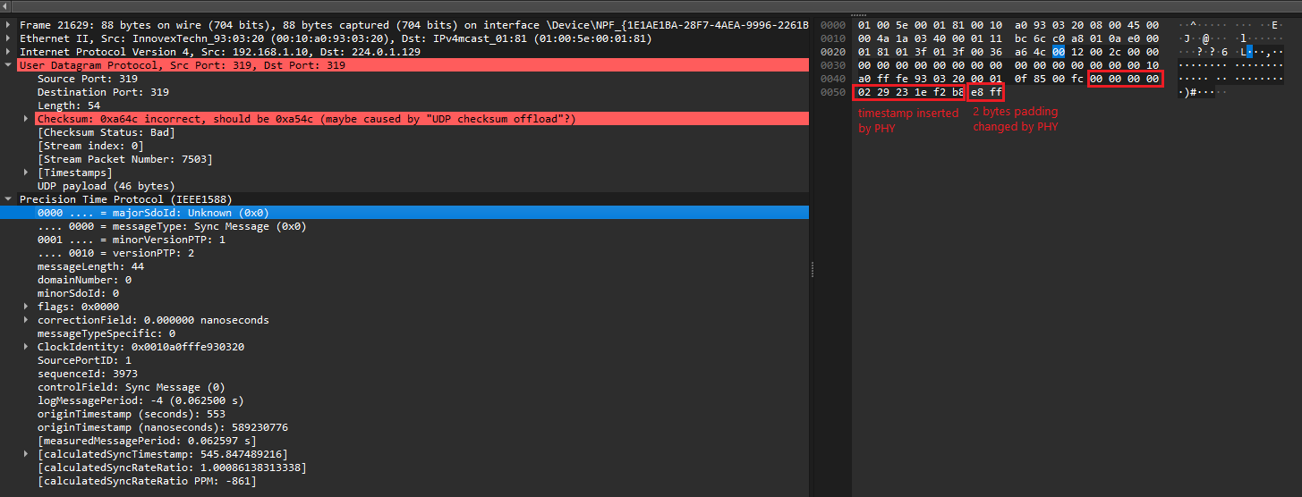
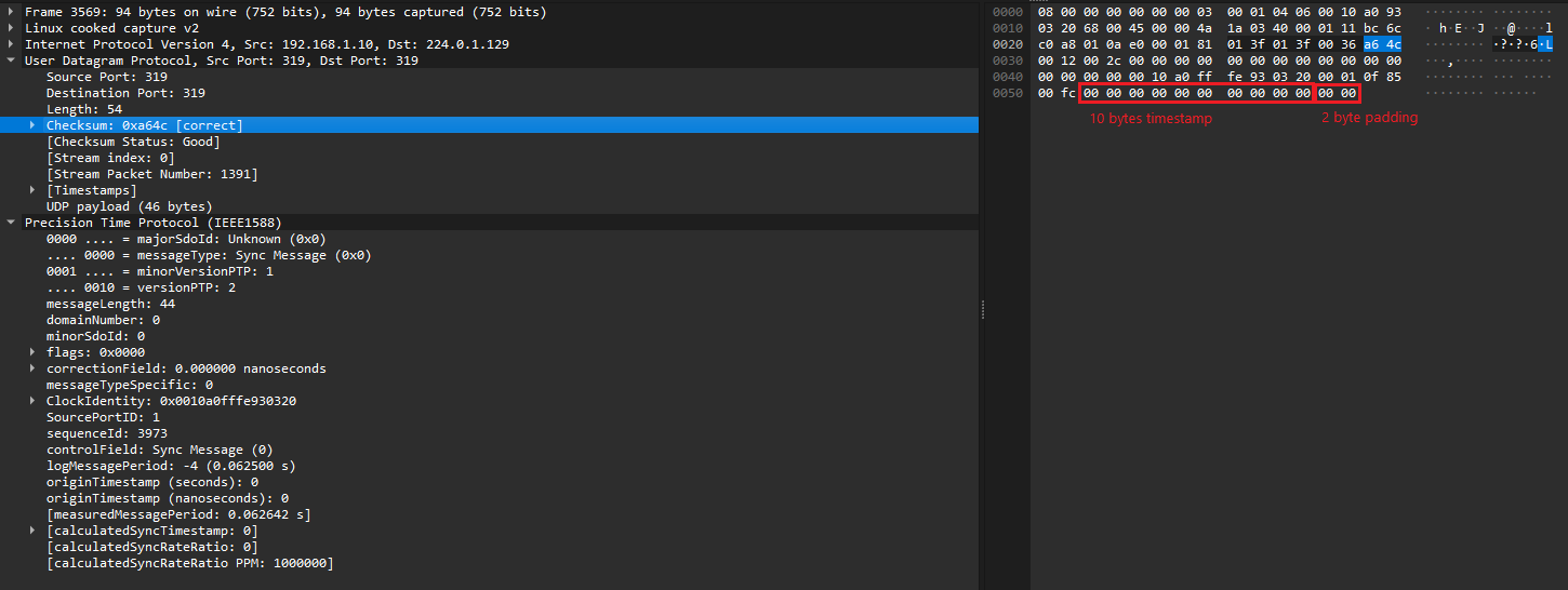
I am using DP83630 chip with Linux system for PTP. I have noticed that occasionally, once in a few hundreds of packets, in case of 1Step sync packets (where the DP83630 inserts correct timestamp and alternates the 2 paddings bytes in order to have correct checksum), the manipulated padding bytes causes the UDP checksum to still be wrong. The wrong UDP checksum is off by 1, for example 0x1538 instead of 0x1539.

Are you familiar with such behavior?

Just to note, I am using DP83630 EVK where the chip still has National Semiconductor logo.

Thanks,

Alexey.

  • just noticed that in all cases of wrong checksum, the inserted padding bytes have 0xff as a last byte

  • Hi Alexey,

    I am not familiar with this behavior, it may be a symptom of clock spec violation, schematic, or layout issues.

    Could you share a block diagram of the application for my understanding?

    Is the PHY behaving as expected otherwise (register access, clk_out is active, ...)?

    Thank you,

    Evan

  • Hi Evan,

    Our test setup consists of DP83630 EVK connected to Microchip SAMA5D3 EDS by using special PCB based adapter that we have designed. The Microchip CPU runs Linux and we are using LinuxPTP package. The DP83630 configured to operate in RMII Master mode. Other than "small" issue above, the PHY behaving as expected.

    Thanks,

    Alexey.

  • Hi Alexey,

    Thanks for clarifying.

    What is the IPG being used for packet transfer? If possible, please try changing IPG and noting if the same padding issue occurs at the same rate.

    Assuming the IPG setting is compatible with DP83630, there are some RMII settings we can configure to help isolate the issue:

    1) 0x17[13] = '1' : Disable RMII TX latency optimization

    TX optimization actively syncs transmit and reference clock phase, disabling may help isolate if the issue is due to clocking violation

    2) 0x17[4] = '1' : Switch to RMII revision 1.0

    Is Microchip CPU using revision 1.0 or 1.2? Mismatched revision may cause interop issues.

    3) Read register 0x17[3:2] after the padding issue is observed.

    Overflow / underflow flagging is a symptom of PPM violation for clock input.

    Thank you,

    Evan

  • Hi,

    I have checked overflow/underflow bits and those are not set. Currently checking other two things you have suggested. Regarding the IPG, does DP83630 requires IPG greater than standard (96 bits for 100Mbit)?

  • Hello,

    Evan is OoO today and will be back tomorrow. 

    Sincerely,

    Gerome

  • Hi Alexey,

    I expect 96bit IPG to work here. Thanks for confirming overflow/underflow bits are not set, this does not seem to be a clocking issue.

    Please let me know results for tests (1) and (2) when possible.

    Thank you,

    Evan

  • Hi Evan,

    I've tried setting both bits, 4 and 13, (one each time) and it didn't help.

    Any other ideas?

    Thanks!

    Alexey.

  • Hi Alexey,

    Thanks for confirming the tests.

    My current assumption is the PHY inserts the correct padding byte, but there is an issue with how the packet is received on the MPU-side.

    For this, I would like to confirm:

    1) DP83640 X1 clock input is 25M +/- 50PPM

    2) MPU is expecting 50M clock input from PHY's CLK_OUT pin, and this is 50M +/- 50PPM when probed on MPU-side

    When you observe the incorrect UDP checksum, this on the software log for the received packets? I'm wondering if there's a way for us to probe/observe on the signal-level if the correct padding is seen on the PHY-side, so we can isolate the issue to the MPU's receiver side.

    Thank you,

    Evan

  • Hi Evan,

    I think there is some misunderstanding here. The DP83640 PHY inserts paddings bytes for checksum correction before it transmits the packets to the Ethernet (PTP SYNC packet). I observe the wrong checksum (wrong padding bytes manipulation) on the reception side which is not DP83830 but standard PC (tried few) connected either directly to DP83630 or through switch. Other packets transmitted from MPU, which DP83630 does not manipulate its checksum or other fields, never has wrong checksum.

    Regarding the clocks - the DP83630 has 25MHz crystal on its X1 and X2 (DP83630 EVK) and it supplies 50MHz clock to the MPU through the RX_CLK pin (according to the datasheet, in case of RMII master mode, the TX_CLK and RX_CLK can be used for providing reference 50MHz clock to the MAC).

    Thanks,

    Alexey.

  • Hi Alexey,

    My mistake, thank you for the clarification.

    I am referring to this software development guide to understand possible causes:

    PHYTER_Software_Development_Guide_v1.96

    Is IPv4 or IPv6 being used, and is the stock reference library being used without changes?

    Thank you,

    Evan

  • Hi Evan,

    IPv4 is being used. Regarding the software, I am using LinuxPTP package ver 4.3 and DP83640 Linux PHY driver that comes in mainland Linux (Kernel ver 6.6).

    Thanks,

    Alexey.

  • Hi Alexey,

    Referring to section 3.1.3.4 in the software development guide, register 0x1D (PTP_RXCFG4, Page 5 space) can be used to configure how UDP checksums are handled for IPv4.

    Do you see a difference in the checksum error rate when setting 0x1D[15] = '0' vs. '1' ?

    Thank you,

    Evan

  • Evan,

    I think the section you have mentioned talks about receive timestamp insertion. My issue is related to TX timestamp insertion and checksum correction which is enabled by bit 9 in PTP_TXCFG0. Do you think changing the RX timestamp insertion as you have suggested can affect the TX timestamp behavior?

    Thanks,

    Alexey.

  • Hi Alexey,

    Apologies again for the confusion.

    I checked again for any history on this behavior, and found a similar case resolved by configuring PTP_TXCFG0:

    Enable both CRC_1STEP and CHK_1STEP bits in 0x16

    Does this resolve the issue?

    Thank you,

    Evan

  • Hi Even,

    I have tried setting CRC_1STEP bit (the CHK_1STEP was already set). It didn't help.

    I have also tried to understand if there is something special in the packets that fail. I can see that all the failed packets have 0xFF as the last byte (second byte of the two byte padding), but not all packets that have 0xFF as the last byte are failed. Note, the 0xFF itself is correct value for the last byte. The byte before last is incorrect in the failed packets. 

    I have also captured the packet that would fail inside MPU before it was sent to the PHY and it is correct (the checksum is correct and the two additional paddings bytes are zeros).

    Thanks

    Alexey.

  • Hi Alexey,

    Thanks for confirming this, I agree that there seems to be some incompatible PHY config that is inserting the wrong padding byte.

    I need to check with the team and see what other configs we can test to resolve this. Apologies for the slow debug here, DP83630 is one of our older PHYs with limited support.

    Thank you,

    Evan

  • Hi Alexey,

    Please reference this thread:

    https://e2e.ti.com/support/interface-group/interface/f/interface-forum/915170/dp83640-invalid-udp-checksum-generated-with-sync_1step

    Noted in solution, can we pad an extra two bytes of 0's and see if checksum error is still present?

    Thank you,

    Evan

  • Hi Evan,

    Do you suggest adding two more padding bytes (on top of two padding byte that I am adding already)? The author in the topic you've suggested didn't add padding bytes at all and the feature not worked for him. In my cases, the checksum is correct most of the times.

    For debugging, I have captured the PTP traffic at the MPU (using TCPdump) before it was sent to the DP83630 PHY and also at the receiver side (PC with Wireshark). I have found the defective packet (with wrong checksum) on the PC and also at the MPU. After analyzing the source packet at the MPU side, it has the two padding zero bytes in the end (and correct checksum assuming zero timestamp and zero padding bytes).

    Thanks,

    Alexey.

  • Hi Alexey,

    Do you suggest adding two more padding bytes (on top of two padding byte that I am adding already)?

    If the frame format for UDP + timestamp data is correct, and the last two padding bytes are used as checksum, this should be sufficient.

    When you observe the defective packet at the MPU and PC side, both sides show two zero bytes for the checksum? My understanding is that DP83640 will modify these last two bytes and correct the checksum if 0x16[10:9] are enabled.

    Could you share a PHY register dump with CRC_1STEP and CHK_1STEP enabled?

    Thank you,

    Evan

  • Hi Evan,

    Here is Wireshark screenshot of "corrupted packet" as received by PC. The UDP checksum is incorrect and the last padding byte is 0xff).

    here is a screenshot of the same packet on the transmitter side (DP83630), captured by tcpdump (of course before the timestamp added by the hardware and padding bytes changed), the checksum is the same as at the received side, the padding bytes and the timestamp are zeros):

    I will share the register dump a little bit later.

    Thanks,

    Alexey.

  • Hi Alexey,

    Is the checksum correct relative to the last two bytes of the packet?

    I see Wireshark is referencing a different byte position for checksum, while the PHY is modifying the last two bytes for checksum. It's unclear to me if the checksum error is an issue with how the PHY is modifying the packet, or with the expected UDP frame format when appending checksum at the end in Wireshark.

    In the latter case, is it possible to change how Wireshark interprets the packet?

    Thank you,

    Evan

  • Evan,

    The different indexes between transmitter and receiver that you see at the screenshots are because of different capture methods (directly by Wireshark at the receiver and by tcpdump at the transmitter), the fields are at correct locations regarding the Ethernet frame itself.

    The transmitter side TCP stack calculates checksum including the 10 zeros as timestamp and 2 padding zeros before it passes the packet to PHY, 0xa64c in our example. The PHY modifies10 bytes of timestamp and modifies the two padding bytes so the checksum will still be correct.

    At the receiver side, the received checksum is still 0xa64c and according to Wireshark (also verified with other tools), the checksum is wrong. This means that the paddings bytes added by PHY are wrong and as I've explained earlier, the padding bytes are almost correct - diffs from the correct one by one point.

    Alexey.

  • Thank you for clarifying this, I agree that PHY's checksum modification has errors here.

    Please test with increased IPG. I'd like to confirm that appended PTP data is not causing errors due to reduced frame gap.

    Thank you,

    Evan

  • Hi Evan,

    Our current Microchip MCU does not allow changing IPG, but we are going to switch to more advanced device very soon. The new device supports IPG configuration, so I will wait until we have new boards ready and continue debug from there.

    Thank you very much,

    Alexey.

  • Hi Alexey,

    Sounds good, please share more details when able.

    Thank you,

    Evan