This thread has been locked.

If you have a related question, please click the "Ask a related question" button in the top right corner. The newly created question will be automatically linked to this question.

TRSF3221E: Schematic review

Part Number: TRSF3221E
Other Parts Discussed in Thread: TMUX7234

Tool/software:

Hello,

     I had asked a question previously about using the TMUX7234 to switch RS232 signal lines.  After doing more research I was able to come up with a design and would like some feedback if at all possible.

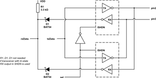
     Referencing the image below and an explanation where someone stated that since the outputs are tri-stated they can be connected together without harming one another.  I have created the schematic layout, which is attached.  Am I missing anything?  Does this design look like it will work?

  • So from the block diagram, I see you have diodes tied to the Rx TTL side. From what I can see, when Rx drives high the diode will pass current but when the Rx drives low nothing happens since you have an external pull up past the diode, there is no path for that node to leak to GND. I think you either need a pull down resistor or you need to flip the diodes to face the Rx outputs. If you flip the diodes, then when you drive low on Rx the signal on the left would go to Vfd of the diode and when you drive high on Rx then the diode stop conducting and the external pull up would bring the node to Vcc. In theory, if one of the device were disable/shutdown by SEL then the diodes probably don't need to be there but having them could prevent any kind of weird timing issue where the device didn't fully disable yet while the other device was on and actively driving the opposite logic.

    -Bobby

  • Hello Bobby,

         While I was away I started thinking about the design and realized I had uploaded an incorrect schematic.  The updated schematic image should match the block diagram (minus D1, D2, and R1 since the transceivers are tri-state outputs).  The original schematic had both transceivers' EN pin attached to the same signal, which defeats the purpose entirely.  

         The DIP switch should flip the NOT gate circuit and alternate which transceiver is active.

  • Hey Billy,

    Just to be sure. Did you have the latest block diagram?

    The current one still has the same issue I highlighted in my first reply. 

    The other thing I need to point out is the same thing Clemens pointed out in the original post where one driver would technically see two receivers when connected through a cable. This would likely limit the max cable distance/speed you can operate at (disabling the device would not remove the receiver's loading).

    -Bobby

  • Hello Bobby,

         I do not have a different block diagram.  I was hoping this model when using EN, FORCEON, and FORCEOFF would disconnect the unused receiver load.

         If I were to use a simple switch what specifications are important?  Would I only need to worry about DCV being >= 30V or would >= 15V work?

         Thank you for your patience!

  • Hi Billy,

    I do not have a different block diagram.  I was hoping this model when using EN, FORCEON, and FORCEOFF would disconnect the unused receiver load.

    No problem, I just figured you would update it after my first post. I don't see the diode in the schematic so I'm not sure if the error from the block diagram carried over to the schematic. 

     If I were to use a simple switch what specifications are important?  Would I only need to worry about DCV being >= 30V or would >= 15V work?

    if the switch (I assume it's a FET switch and not a mechanical dip switch) is being used on the RS232 side, you would probably need to ensure it can handle the negative rail swings that RS232 can see. receivers are spec'd to usually +/-25V sometimes +/-30V but our drivers are spec'd for around +/-13V. So I would assume for a switch you would want to pick the wider range of +/-25V for a more robust solution but choosing +/-15V would probably work. Aside from this, maybe make sure the ESD ratings also match or exceed the device's unless you have external. 

    -Bobby