This thread has been locked.

If you have a related question, please click the "Ask a related question" button in the top right corner. The newly created question will be automatically linked to this question.

TUSB9261-Q1: TUSB9261 can be programmed but not working

Part Number: TUSB9261-Q1
Other Parts Discussed in Thread: TUSB9261, TUSB9260, SN74HCT244

Tool/software:

Hello there,

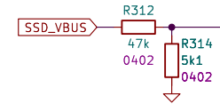
I designed my own board with TUSB9261 chip, external 40MHz clock source (not crystal) and M.2 SSD slot. Also in my circuit I can flash SPI memory without interferences from TUSB9261. There is a bidirectional quad switch. All other components are exactly this same as in evaluation board. Board is self powered with power sequention where 3V3 is enabled for bridge and M.2 at the same time. nGRST signal getting high after some miliseconds after 3V3.

I've bypassed that SPI switch (and desoldered it) for maximum straight connection betwen SPI memory and SATA bridge.

I've checked power sequention and clock source freq and there are perfectly fine.

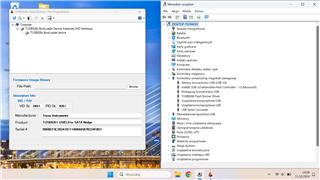
Bridge in Device Manager have name TUSB9260 (like older brother). Btw. Windows 11 only. That's weird because chip is 9261.

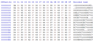
On SPI signals I'm seeing sequention on start "0x05 0x00 0x00" and "0x03 0x00 0x00 0x00 0x00 0x00 0x00" on MISO and MOSI at the same time.

On SATA there is no any signal.

Pin GPIO10 named SATA_EN have lower than 0,5V.

I've tried to use TUSB9260 and TUSB9261 burning software with pin swapping but without any results.

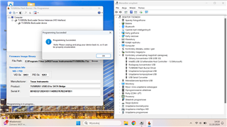
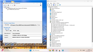
I can program succesfully but I'm not seeing SATA disk in Windows and SATA signals on board. Firmware 1.06v

What I can check next to make it works?

It is possible to flash SPI memory separatelly?

  • Also there is no any communication on UART. It is setted to 115200 baudrate?

  • Hi Rafal,

    Do you have a schematic of your design that you can share?  Does the oscillator meet the oscillator specification in the datasheet?  

    nGRST signal getting high after some miliseconds after 3V3.

    Can you confirm this is greater than 1ms and less than 100ms?

    Pin GPIO10 named SATA_EN have lower than 0,5V.

    This is strange.  Let me check the EVM here and see the voltage.

    It is possible to flash SPI memory separatelly?

    Yes, you can program the SPI memory before putting the device on the board.

    Thanks,

    Nicholaus

  • Hi Nicholaus,

    I can confirm that high level on nGRST is high after something around 15ms. Crystal looks like is in specs (YSO110TR). I can't define precise that clock signal have voltages in specs because my oscilloscope can handle freq up to 50MHz.

    Can You send me that firmware? I prefer version without TX swap but this is not necessary because I have some resistors to select TX connection type.

    On the schematic signals PG_1V1 and PG_3V3 are delivered by power sequencer as one of the last signals in system. FREQ_SEL_CFGx and SELF_PWR_CFG are shorted to 3V3.

    7080.schematic.pdf

  • HI Rafal,

    The firmware is available on the product page: TUSB9261 data sheet, product information and support | TI.com

    On the schematic signals PG_1V1 and PG_3V3 are delivered by power sequencer as one of the last signals in system.

    The nGRST is high for 15ms after the power is delivered to the system?

    I'll review the schematic and follow up.

    Regards,

    Nicholaus

  • No, I have sequencer that swithing DC/DC controllers (1V1 first, 3V3 second etc.). Every channel of that sequencer is delayed by 10-20ms. That PG signals are also delayed so nGRST have high level after 15ms only when that two crucial supply voltages occurs.

    This is not for 15ms.

    That SLC416 and SLC421 don't need to be uploaded by Flash Burner? U1/U2 disabled or enabled ... what's the difference?

    Regards,

    Rafal

  • I've tried to flash SPI memory with .bin files. There is no significant differences. Still TUSB926x is showed in Bootloader Mode. On SPI lines I have sequence 0xff 0x00 0x00 on MISO, 0x05 0x00 0x00, on MOSI and after 8us 0x00 0x00 0x00 0x00 0x18 0xd6 0x00 on MISO, 0x03 0x00 0x00 0x00 0x00 0x00 0x00 on MOSI.

  • Rafal,

    U1 and U2 are USB low power states.  I would choose the U1/U2 disabled firmware for now.

    Can you take a screenshot of the TUSB926x in bootloader mode on Device Manager and the FlashBurner?  After uploading the firmware this should change.  Does the UI say that it has successfully programmed the device?

    R312 should be 90.9K and R314 should be 10K as described in section 8.2.1 in the datasheet.

    Regards,

    Nicholaus

  • I agree that values of resistor device. But I think that when we have 90k9 and 10k from datasheet for 5V we have 496mV on the input. In my case 489mV. Is it that the USB_VBUS is so poor designed it needs so precise impedance? As we know USB VBUS voltage in many cases can drop below 4V8, this is not that case. Strange

    Here You have screenshots. As You can see that the chip looks like there is nothing changed and new drive is not visible.

  • Hi Rafal,

    No, I wouldn't think so, but it is recommended in the datasheet.

    Thanks for the screenshots.  It does seem like the BootLoader driver is working properly, but the SPI firmware is not being retrieved from the MX25L512E. I'm reviewing the information up until now with that in mind and will follow up before EOD.

    Regards,

    Nicholaus

  • Hi Nocholaus

    Thank You, I will wait for some new ideas. I think I checked all things I have to check alone without support.

    Regards,

    Rafal

  • Hi Rafal,

    Rafal_SchReview.pdf

    Here is a review.  I'm wondering if the SN74HCT244 MUX may be interfering with the SPI interface as it does not have bandwidth information included in it's datasheet.

    Do you have more SPI decode information, and where are you probing to read the MOSI and MISO signals?  Above are the hex values for the default firmware.

    Regards,

    Nicholaus

  • Hi Nicholaus,

    I knew that You will ask about the SPI mux/switch. I''ve tested programming with and without mux. As You can see on my schematic I added jumpers (JP305, 306, 308, 309) to make direct connection between TUSB and Flash. In this moment (from start of the topic) I have desoldered this mux. I'm probing signals with J201 connector. When I'm programming I'm "unshorting" that jumpers. I have 4ch DSO with SPI analysis. All traces have less that 50mm length without stubs (connector is between TUSB and Flash). This is 6-layer board with proper stackup and impedance controlled traces (for SPI 50 Ohms).

    Regards,

    Rafal

  • Thank You for that review file by the way. I need to confirm ... that chip can handle connection on USB 2.0 with slower SATA speed, is it right? I'm seeing that in defaults UART pins are configured as GPIO. So if that chip is not programmed properly I won't see any data in therminal? Does nGRST have Schmitt's trigger or is it basic CMOS input?

  • Hi Rafal,

    It can work on USB 2.0 speeds, and I have tested this in the lab previously.  The UART pins are GPIO by default so yes, if it's not programmed I wouldn't expect to see data on the UART interface.

    I'm not sure on the nGRST pin.  I'll need to check internally to see if there is any information on it.  Why do you ask?

    Regards,

    Nicholaus

  • Hi Nicholaus,

    I'm asking because I can easily regulate slope on that pin with additional capacitor (I can cutoff jumper JP301) to maybe see some changes. But if that pin isn't Schmitt's trigger it can work inproperly. Is that make any sense?

    Regards,

    Rafal

  • Hi Rafal,

    Yes.  I couldn't find specific information on the internal design of the GRSTz pin, but the spec for digital I/O in the datasheet says it has 200mV of hysteresis. GRSTz has the added requirement that it is 2V (deasserted) at least 2ms after 1.1V and 3.3V power is stable.

    Regards,

    Nicholaus

  • Hi Nicholaus,

    I found it! That was USB Hub based on TUSB2046. That's wierd because I can handle all devices connected to it but not this. Maybe because of USB speed specification. For me It looked like I can communicate with all devices connected to that hub and in device manager as You know all is looking good. Another thing that made us confused were programming success windows.

    When I received PCB assembled I had some other issues also with TUSB9261 (programming failed everytime then). The first moment then I achieved "successful" flashing was when bridge was connected through TUSB2046.

    I don't need max speed but only high capacity so USB 2.0 12Mbps is enough.

    Thank You for all suggestions.

    Regards,

    Rafal

  • Hi Rafal,

    Great!  Glad you found it.  That is strange, and I wonder what the root cause is, but it sounds like the issue is resolved for now.  Let me know if you have any other under questions.  I will close the issue if there are no others.

    Regards,

    Nicholaus

  • Hi, thank You ... I will thinking about this for next few days and I will reply again. I have to do some stability tests.

    Regards,

    Rafal

  • Alright, I'll leave it open.

    Thanks,

    Nicholaus

  • Hi Nicholaus,

    I have all informations ... every bridge is working stable so I think this can be end of the topic. I have only one last question. On 2 of 9 boards bridge can't handle USB 3.0 but every trace and component are good (input impedances are good). Do You think are they broken?

    Many thanks

    Regards,

    Rafal

  • HI Rafal,

    If 2 out of the 9 are broken then my first thought would be that something in the system is different.  Is each test using the same USB cables or are they different?  Is anything else different between the failing and passing cases?

    Regards,

    Nicholaus