This thread has been locked.

If you have a related question, please click the "Ask a related question" button in the top right corner. The newly created question will be automatically linked to this question.

DS125MB203: The default setting when use Pin control

Part Number: DS125MB203
Other Parts Discussed in Thread: USB2ANY

Tool/software:

Hi team,

This is Jayden, FAE for ZTE. ZTE is using DS125MB203SQ/NOPB in 5G wireless infrastructure project.  And they have some questions for this device when used in 10Gbps serdes link.

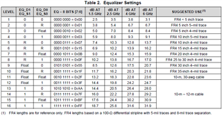
  1. As they don't have resources for SMBus control, so they want to use pin control.  Can they use this device to support 10Gbps Serdes link ? What is the default CTLE amplification gain (dB)?
  2. I find that the mode pin can be configured to support PCLE、10GE、10-KR protocol. If ZTE needs to support other protocols, what should the mode pin be configured to? For example, the CPIR protocol in the communication system.
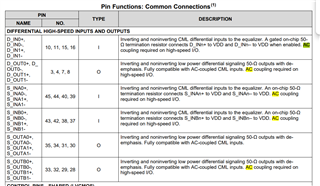
  3. Both the input and out need the AC coupling capacitor. What's the recommend value for these two capacitor?

Brs

Jayden

  • Hi Jayden,

    1. Pin control likely can be used to support this application, however I recommend performing high-speed simulation with the IBIS-AMI model to confirm settings available in pin mode will be sufficient for this use case. The IBIS-AMI model is available on the product site.

    I also recommend designing a resistor option on the ENSMB pin to configure SMBus mode as well as SDA/SCL access headers. SMBus mode can be very helpful for debug purposes and the access headers can be connected to an external USB2ANY or other SMBus/I2C controller.

    Please refer to the Equalizer Settings table in the datasheet. CTLE gain is configurable by input voltage level on the EQ_Dx and EQ_Sx pins. The optimal level will be dependent on the insertion loss on the transmission channel.

    2. The MODE pin description is a bit unclear. Each setting adjusts the signal chain and is not required to be used with the protocols listed.

    • 0: Limiting mode. Configures the signal chain with limiting characteristics best suited for PCIe Gen1/2 and 10GE.
    • Float: Auto mode. The redriver detects the incoming data rate and selects limiting mode for PCIe Gen1/2 rates or linear mode for PCIe Gen3 rate. Intended for use with PCIe applications only.
    • 1: Linear mode. Configures the signal chain with input-to-output waveform linearity. Linear mode is optimal for passing through feedback protocols such as link training and auto-negotiation and is best suited for PCIe Gen3 and 10G-KR.

    I am unfamiliar with CPIR protocol and therefore cannot recommend which mode is better suited at this time.

    3. We recommend using AC coupling capacitors in the range of 100nF to 220nF with a footprint size of 0402 or smaller.

    Best,

    Lucas