This thread has been locked.

If you have a related question, please click the "Ask a related question" button in the top right corner. The newly created question will be automatically linked to this question.

DP83825I: DP83825I: Issue at Slave Mode Communication

Part Number: DP83825I


Tool/software:

We are using TI DP83825I Ethernet Phy in RMII Slave configuration with Ambarella CV25 SOC running Linux Kernel 5.4.

We were able to make the Ethernet work in RMII Master mode with the following device tree bindings configuration. The pinctrls, power and reset gpios are configured correctly according to the board.

DTSI:
mac0: ethernet@e000e000 {
            compatible = "ambarella,eth";
            #address-cells = <1>;
            #size-cells = <0>;
            reg = <0xe000e000 0x2000>;
            interrupts = <0 58 0x4>;
            pinctrl-names = "default";
            pinctrl-0 = <&rmii_pins>;
            phy-mode = "rmii";
            amb,rct-regmap = <&rct_syscon>;
            amb,scr-regmap = <&scratchpad_syscon>;
            amb,tx-ring-size = <32>;
            amb,rx-ring-size = <64>;
            amb,ipc-tx;
            amb,ipc-rx;
            amb,enhance;
            amb,ahb-12mhz-div = <5>;
            clock-names = "ptp_ref";
            clocks= <&osc>;
};


DTS:
mac0: ethernet@e000e000 {
            status = "ok";
            pinctrl-0 = <&rmii_pins &enet_2nd_ref_clk_pins_a>;
            phy-mode = "rmii";
            amb,tx-clk-invert;
            phy@0 {
                reg = <0>;
                pwr-gpios = <&gpio 94 0x1>;
                rst-gpios = <&gpio 35 0x0>;
                txen-skew-ps = <0>;
                rxdv-skew-ps = <0>;
                rxd0-skew-ps = <0>;
                rxd1-skew-ps = <0>;
                rxd2-skew-ps = <0>;
                rxd3-skew-ps = <0>;
                txd0-skew-ps = <0>;
                txd1-skew-ps = <0>;
                txd2-skew-ps = <0>;
                txd3-skew-ps = <0>;
            };
};

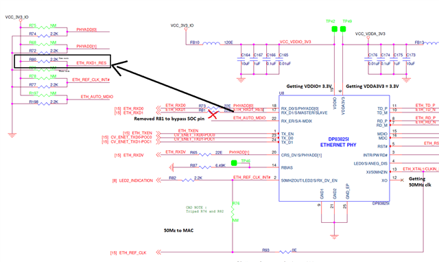
We are not able to make the Ethernet work in RMII Slave Mode, "eth0" interface is up with IP Address but ping is not working.

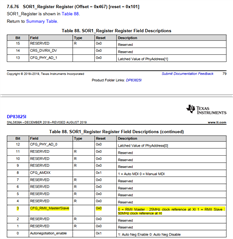
We have set "RX_D1" as "1" for DP83825I from hardware configuration. We have made sure the 50 MHz clock is given to the TI DP83825I PHY for slave operation. Also the same 50 MHz clock is given to the MAC.

We are getting the following output of ifconfig, ethtool and ip commands when configured in slave mode.

# ifconfig
eth0      Link encap:Ethernet  HWaddr 2E:35:35:4D:41:BF  
          inet addr:192.168.1.250  Bcast:192.168.1.255  Mask:255.255.255.0
          UP BROADCAST MULTICAST  MTU:1500  Metric:1
          RX packets:0 errors:0 dropped:0 overruns:0 frame:0
          TX packets:0 errors:0 dropped:0 overruns:0 carrier:0
          collisions:0 txqueuelen:1000
          RX bytes:0 (0.0 B)  TX bytes:0 (0.0 B)
          Interrupt:28

lo        Link encap:Local Loopback  
          inet addr:127.0.0.1  Mask:255.0.0.0
          UP LOOPBACK RUNNING  MTU:65536  Metric:1
          RX packets:0 errors:0 dropped:0 overruns:0 frame:0
          TX packets:0 errors:0 dropped:0 overruns:0 carrier:0
          collisions:0 txqueuelen:1000
          RX bytes:0 (0.0 B)  TX bytes:0 (0.0 B)

# ethtool eth0
Settings for eth0:
        Supported ports: [ TP MII ]
        Supported link modes:   Not reported
        Supported pause frame use: Symmetric Receive-only
        Supports auto-negotiation: No
        Advertised link modes:  Not reported
        Advertised pause frame use: No
        Advertised auto-negotiation: No
        Speed: 10Mb/s
        Duplex: Half
        Port: MII
        PHYAD: 0
        Transceiver: internal
        Auto-negotiation: off
        Current message level: 0x00000001 (1)
                               drv
        Link detected: no
# ip a
1: lo: <LOOPBACK,UP,LOWER_UP> mtu 65536 qdisc noqueue qlen 1000
    link/loopback 00:00:00:00:00:00 brd 00:00:00:00:00:00
    inet 127.0.0.1/8 scope host lo
       valid_lft forever preferred_lft forever
2: eth0: <NO-CARRIER,BROADCAST,MULTICAST,UP> mtu 1500 qdisc pfifo_fast qlen 1000
    link/ether 2e:35:35:4d:41:bf brd ff:ff:ff:ff:ff:ff
    inet 192.168.1.250/24 brd 192.168.1.255 scope global noprefixroute eth0
       valid_lft forever preferred_lft forever


Loopback ping is working in slave mode:
# ping 127.0.0.1
PING 127.0.0.1 (127.0.0.1): 56 data bytes
64 bytes from 127.0.0.1: seq=0 ttl=64 time=0.132 ms
64 bytes from 127.0.0.1: seq=1 ttl=64 time=0.049 ms


Can you please tell what DTSI/DTS changes from software need to be done for RMII Slave Mode operation?

  • Hi Dhruvish,

    DP8382x.c driver on Kernel v5.4 does not support RMII master/slave config via DTS.

    The device strap with RX_D1 = '1' is sufficient to set RMII slave mode, I suspect either a clocking or strap issue on startup.

    Can you please help confirm:

    1) 50M is seen on PHY and MAC input clock

    2) PHY register 0x17[7] = '1'

    For the working case in RMII master mode, were there hardware changes for proper clock config? (25M input to PHY, 50M recovered clock sent to MAC)

    Thank you,

    Evan

  • Hi Evan, 
    Thanks for quick response. 

    1. Yes we are 50MHz clock we are able to see on PHY and MAC. 
    2. We are not able to read any resistor using mdio.  each resistor we are getting value as 0x0000. 

    3. Our device is working fine in Master mode. we are providing the 25MHz clock from the Host and 50MHz recovered clock send to MAC.

  • Hi Dhruvish,

    1) Thanks for confirming.

    2) I'm unclear how MDIO read is failing, as the system is able to bind PHY driver and configure device using DTS. Can you share the method you are using for register access? During boot, do you see DP83822 driver binding? (dmesg | grep "mdio")

    3) In this case, I suspect there is an issue with the strap for RMII slave mode taking effect. We will need to read PHY register 0x17 to confirm which mode is being set via strap.

    Thank you,

    Evan

  • Hi Evan, 
    Please find my response for point 2 and 3. 

    • With command dmesg | grep "mdio" nothing is coming
    • mdio r eth0 0x0001 : In mdio read all the values getting 0x0000
    • mdio r eth0 0x17 : In mdio read all the values getting 0x0000
  • Hi Dhruvish,

    The PHY driver is not binding in this case, so I do not expect any DTS configuration to take effect.

    To debug this, please help confirm:

    • PHY address is strapped to '0'
    • MDC/MDIO signals are seen on processor-side during boot

    Thank you,

    Evan

  • Hi Evan, 
    We have measured PHY address is strapped to '0'.

    We are not able to catch any signal on MDC/MDIO pins. 

  • Hi Dhruvish,

    Is the PHY powered properly with 50M input clock on XI?

    I expect some MDC/MDIO transaction on the line during boot, if the PHY is alive.

    To confirm this, please:

    • Share scopeshot of XI on PHY-side
    • Confirm RX_D1 = '1' strap is taking effect
    • Probe voltage across RBIAS resistor, approx ~1V?

    Thank you,

    Evan

  • Hi Evan,

    • RXD1 = '0' we are getting. From HW we have added pullup but during bootup SOC itself making it down.
    • During boot we are getting some transactions on the MDIO line.
    • We are getting voltage across RBIAS resistor = 0V. But we are getting this 0V in master made as well. And master mode is working fine.
    • Please check below scopeshot of XI on phy side.
  • Hi Amol,

    Thank you for confirming the test results.

    If RXD1 strap is pulled down by SoC, driver binding and register access will fail as the device defaults into RMII master mode and expects 25M clock on XI.

    The PHY cannot operate unless compatible XI is provided, relative to RMII master (25M) or slave (50M) mode.

    Is it possible to power the PHY first before the SoC, to ensure RX_D1 is strapped high before SoC drives the pin low?

    Thank you,

    Evan

  • Hi Evan,

    We tried to make the RXD1 pin as '1' during boot up. We have probe the signal as well & getting '1' but after some time it is getting '0' because same pin is going to be used as RXD1 in ethernet communication. Upto what time we need to keep this pin High to make it as strapped ?

  • Hi Amol,

    The PHY needs around ~250ms to latch strap values after power rails have ramped.

    To confirm the strap is being set correctly:

    • Is 3.3V or 1.8V VDDIO being used?
    • What is the voltage seen at the pin on power-up (before MAC drives it low)?
    • After PHY power rails ramp, how much time passes before MAC drives pin low?

    Thank you,

    Evan

  • Hi Evan, 


    1. we have used 3.3V as VDDIO. 

    2. We are getting 3.3V at pin before MAC drive it low. 
    3. After PHY power up rails for 40ms this is getting 3.3V before MAC drive it low. 
    we will try to increase the delay 250ms as your suggestion and test it. 

  • Hi Dhruvish,

    Thanks for confirming.

    Looking forward to see results with increased delay for MAC driving pin low.

    Thank you,

    Evan

  • Hi Evan,

    We have bypass the SOC pin & monitor the strapping pin RXD1. We observed that phy itself making it low after 40mS. Can you please guide further ?

  • Hi Amol,

    I may be mistaken about the timing before PHY begins driving the output pin, but if SoC is not connected then this strap should be setting properly.

    In this case, are you able to access the PHY registers through MDC/MDIO?

    The key test plan is:

    1) Verify SoC is not driving the pin low on start-up so device straps into RMII slave mode properly. 

    2) Read back PHY register dump to confirm PHY has the correct configuration for communication

    Thank you,

    Evan

  • Hi Evan,

    Please see below response over test plan 

    1) We have isolated the path from SOC to this RXD1 pin & verified that SOC is not driving the pin low. The phy itself is making it low.

    2) We tried to access the PHY registers using MDC/MDIO but not getting the correct data. Every register which we tried to read it is getting 0x00.

    Can you please share your thoughts on below queries ?

    1) Is there any special command to read the phy registers using MDC/MDIO ? We have the commands but still to cross verify please share the command also.

    2) Did you checked the slave mode communication at your end ? Is this working ?

    3) Please refer to the below attached image. We have removed the R81 to isolate the SOC pin. In this case only pullup will be there on the RXD1 pin so it should be HIGH by default but it is getting HIGH only for 35~40ms & after that it is getting LOW.

  • Hi, 
    We are Using below attached driver. Please check this as well. If any upgrade or changes are required in it. 


    // SPDX-License-Identifier: GPL-2.0
    /*
     * Driver for the Texas Instruments DP83822 PHY
     *
     * Copyright (C) 2017 Texas Instruments Inc.
     */
    
    #include <linux/ethtool.h>
    #include <linux/etherdevice.h>
    #include <linux/kernel.h>
    #include <linux/mii.h>
    #include <linux/module.h>
    #include <linux/of.h>
    #include <linux/phy.h>
    #include <linux/netdevice.h>
    
    #define DP83822_PHY_ID	        0x2000a240
    #define DP83825I_PHY_ID		0x2000a150
    
    #define DP83822_DEVADDR		0x1f
    
    #define MII_DP83822_PHYSCR	0x11
    #define MII_DP83822_MISR1	0x12
    #define MII_DP83822_MISR2	0x13
    #define MII_DP83822_RESET_CTRL	0x1f
    
    #define DP83822_HW_RESET	BIT(15)
    #define DP83822_SW_RESET	BIT(14)
    
    /* PHYSCR Register Fields */
    #define DP83822_PHYSCR_INT_OE		BIT(0) /* Interrupt Output Enable */
    #define DP83822_PHYSCR_INTEN		BIT(1) /* Interrupt Enable */
    
    /* MISR1 bits */
    #define DP83822_RX_ERR_HF_INT_EN	BIT(0)
    #define DP83822_FALSE_CARRIER_HF_INT_EN	BIT(1)
    #define DP83822_ANEG_COMPLETE_INT_EN	BIT(2)
    #define DP83822_DUP_MODE_CHANGE_INT_EN	BIT(3)
    #define DP83822_SPEED_CHANGED_INT_EN	BIT(4)
    #define DP83822_LINK_STAT_INT_EN	BIT(5)
    #define DP83822_ENERGY_DET_INT_EN	BIT(6)
    #define DP83822_LINK_QUAL_INT_EN	BIT(7)
    
    /* MISR2 bits */
    #define DP83822_JABBER_DET_INT_EN	BIT(0)
    #define DP83822_WOL_PKT_INT_EN		BIT(1)
    #define DP83822_SLEEP_MODE_INT_EN	BIT(2)
    #define DP83822_MDI_XOVER_INT_EN	BIT(3)
    #define DP83822_LB_FIFO_INT_EN		BIT(4)
    #define DP83822_PAGE_RX_INT_EN		BIT(5)
    #define DP83822_ANEG_ERR_INT_EN		BIT(6)
    #define DP83822_EEE_ERROR_CHANGE_INT_EN	BIT(7)
    
    /* INT_STAT1 bits */
    #define DP83822_WOL_INT_EN	BIT(4)
    #define DP83822_WOL_INT_STAT	BIT(12)
    
    #define MII_DP83822_RXSOP1	0x04a5
    #define	MII_DP83822_RXSOP2	0x04a6
    #define	MII_DP83822_RXSOP3	0x04a7
    
    /* WoL Registers */
    #define	MII_DP83822_WOL_CFG	0x04a0
    #define	MII_DP83822_WOL_STAT	0x04a1
    #define	MII_DP83822_WOL_DA1	0x04a2
    #define	MII_DP83822_WOL_DA2	0x04a3
    #define	MII_DP83822_WOL_DA3	0x04a4
    
    /* WoL bits */
    #define DP83822_WOL_MAGIC_EN	BIT(0)
    #define DP83822_WOL_SECURE_ON	BIT(5)
    #define DP83822_WOL_EN		BIT(7)
    #define DP83822_WOL_INDICATION_SEL BIT(8)
    #define DP83822_WOL_CLR_INDICATION BIT(11)
    
    static int dp83822_ack_interrupt(struct phy_device *phydev)
    {
    	int err;
    
    	err = phy_read(phydev, MII_DP83822_MISR1);
    	if (err < 0)
    		return err;
    
    	err = phy_read(phydev, MII_DP83822_MISR2);
    	if (err < 0)
    		return err;
    
    	return 0;
    }
    
    static int dp83822_set_wol(struct phy_device *phydev,
    			   struct ethtool_wolinfo *wol)
    {
    	struct net_device *ndev = phydev->attached_dev;
    	u16 value;
    	const u8 *mac;
    
    	if (wol->wolopts & (WAKE_MAGIC | WAKE_MAGICSECURE)) {
    		mac = (const u8 *)ndev->dev_addr;
    
    		if (!is_valid_ether_addr(mac))
    			return -EINVAL;
    
    		/* MAC addresses start with byte 5, but stored in mac[0].
    		 * 822 PHYs store bytes 4|5, 2|3, 0|1
    		 */
    		phy_write_mmd(phydev, DP83822_DEVADDR, MII_DP83822_WOL_DA1,
    			      (mac[1] << 8) | mac[0]);
    		phy_write_mmd(phydev, DP83822_DEVADDR, MII_DP83822_WOL_DA2,
    			      (mac[3] << 8) | mac[2]);
    		phy_write_mmd(phydev, DP83822_DEVADDR, MII_DP83822_WOL_DA3,
    			      (mac[5] << 8) | mac[4]);
    
    		value = phy_read_mmd(phydev, DP83822_DEVADDR,
    				     MII_DP83822_WOL_CFG);
    		if (wol->wolopts & WAKE_MAGIC)
    			value |= DP83822_WOL_MAGIC_EN;
    		else
    			value &= ~DP83822_WOL_MAGIC_EN;
    
    		if (wol->wolopts & WAKE_MAGICSECURE) {
    			phy_write_mmd(phydev, DP83822_DEVADDR,
    				      MII_DP83822_RXSOP1,
    				      (wol->sopass[1] << 8) | wol->sopass[0]);
    			phy_write_mmd(phydev, DP83822_DEVADDR,
    				      MII_DP83822_RXSOP2,
    				      (wol->sopass[3] << 8) | wol->sopass[2]);
    			phy_write_mmd(phydev, DP83822_DEVADDR,
    				      MII_DP83822_RXSOP3,
    				      (wol->sopass[5] << 8) | wol->sopass[4]);
    			value |= DP83822_WOL_SECURE_ON;
    		} else {
    			value &= ~DP83822_WOL_SECURE_ON;
    		}
    
    		value |= (DP83822_WOL_EN | DP83822_WOL_INDICATION_SEL |
    			  DP83822_WOL_CLR_INDICATION);
    		phy_write_mmd(phydev, DP83822_DEVADDR, MII_DP83822_WOL_CFG,
    			      value);
    	} else {
    		value = phy_read_mmd(phydev, DP83822_DEVADDR,
    				     MII_DP83822_WOL_CFG);
    		value &= ~DP83822_WOL_EN;
    		phy_write_mmd(phydev, DP83822_DEVADDR, MII_DP83822_WOL_CFG,
    			      value);
    	}
    
    	return 0;
    }
    
    static void dp83822_get_wol(struct phy_device *phydev,
    			    struct ethtool_wolinfo *wol)
    {
    	int value;
    	u16 sopass_val;
    
    	wol->supported = (WAKE_MAGIC | WAKE_MAGICSECURE);
    	wol->wolopts = 0;
    
    	value = phy_read_mmd(phydev, DP83822_DEVADDR, MII_DP83822_WOL_CFG);
    
    	if (value & DP83822_WOL_MAGIC_EN)
    		wol->wolopts |= WAKE_MAGIC;
    
    	if (value & DP83822_WOL_SECURE_ON) {
    		sopass_val = phy_read_mmd(phydev, DP83822_DEVADDR,
    					  MII_DP83822_RXSOP1);
    		wol->sopass[0] = (sopass_val & 0xff);
    		wol->sopass[1] = (sopass_val >> 8);
    
    		sopass_val = phy_read_mmd(phydev, DP83822_DEVADDR,
    					  MII_DP83822_RXSOP2);
    		wol->sopass[2] = (sopass_val & 0xff);
    		wol->sopass[3] = (sopass_val >> 8);
    
    		sopass_val = phy_read_mmd(phydev, DP83822_DEVADDR,
    					  MII_DP83822_RXSOP3);
    		wol->sopass[4] = (sopass_val & 0xff);
    		wol->sopass[5] = (sopass_val >> 8);
    
    		wol->wolopts |= WAKE_MAGICSECURE;
    	}
    
    	/* WoL is not enabled so set wolopts to 0 */
    	if (!(value & DP83822_WOL_EN))
    		wol->wolopts = 0;
    }
    
    static int dp83822_config_intr(struct phy_device *phydev)
    {
    	int misr_status;
    	int physcr_status;
    	int err;
    
    	if (phydev->interrupts == PHY_INTERRUPT_ENABLED) {
    		misr_status = phy_read(phydev, MII_DP83822_MISR1);
    		if (misr_status < 0)
    			return misr_status;
    
    		misr_status |= (DP83822_ANEG_COMPLETE_INT_EN |
    				DP83822_DUP_MODE_CHANGE_INT_EN |
    				DP83822_SPEED_CHANGED_INT_EN |
    				DP83822_LINK_STAT_INT_EN |
    				DP83822_ENERGY_DET_INT_EN |
    				DP83822_LINK_QUAL_INT_EN);
    
    		err = phy_write(phydev, MII_DP83822_MISR1, misr_status);
    		if (err < 0)
    			return err;
    
    		misr_status = phy_read(phydev, MII_DP83822_MISR2);
    		if (misr_status < 0)
    			return misr_status;
    
    		misr_status |= (DP83822_JABBER_DET_INT_EN |
    				DP83822_WOL_PKT_INT_EN |
    				DP83822_SLEEP_MODE_INT_EN |
    				DP83822_MDI_XOVER_INT_EN |
    				DP83822_LB_FIFO_INT_EN |
    				DP83822_PAGE_RX_INT_EN |
    				DP83822_ANEG_ERR_INT_EN |
    				DP83822_EEE_ERROR_CHANGE_INT_EN);
    
    		err = phy_write(phydev, MII_DP83822_MISR2, misr_status);
    		if (err < 0)
    			return err;
    
    		physcr_status = phy_read(phydev, MII_DP83822_PHYSCR);
    		if (physcr_status < 0)
    			return physcr_status;
    
    		physcr_status |= DP83822_PHYSCR_INT_OE | DP83822_PHYSCR_INTEN;
    
    	} else {
    		err = phy_write(phydev, MII_DP83822_MISR1, 0);
    		if (err < 0)
    			return err;
    
    		err = phy_write(phydev, MII_DP83822_MISR2, 0);
    		if (err < 0)
    			return err;
    
    		physcr_status = phy_read(phydev, MII_DP83822_PHYSCR);
    		if (physcr_status < 0)
    			return physcr_status;
    
    		physcr_status &= ~DP83822_PHYSCR_INTEN;
    	}
    
    	return phy_write(phydev, MII_DP83822_PHYSCR, physcr_status);
    }
    
    static int dp83822_config_init(struct phy_device *phydev)
    {
    	int value;
    
    	value = DP83822_WOL_MAGIC_EN | DP83822_WOL_SECURE_ON | DP83822_WOL_EN;
    
    	return phy_write_mmd(phydev, DP83822_DEVADDR, MII_DP83822_WOL_CFG,
    	      value);
    }
    
    static int dp83822_phy_reset(struct phy_device *phydev)
    {
    	int err;
    
    	err = phy_write(phydev, MII_DP83822_RESET_CTRL, DP83822_HW_RESET);
    	if (err < 0)
    		return err;
    
    	dp83822_config_init(phydev);
    
    	return 0;
    }
    
    static int dp83822_suspend(struct phy_device *phydev)
    {
    	int value;
    
    	value = phy_read_mmd(phydev, DP83822_DEVADDR, MII_DP83822_WOL_CFG);
    
    	if (!(value & DP83822_WOL_EN))
    		genphy_suspend(phydev);
    
    	return 0;
    }
    
    static int dp83822_resume(struct phy_device *phydev)
    {
    	int value;
    
    	genphy_resume(phydev);
    
    	value = phy_read_mmd(phydev, DP83822_DEVADDR, MII_DP83822_WOL_CFG);
    
    	phy_write_mmd(phydev, DP83822_DEVADDR, MII_DP83822_WOL_CFG, value |
    		      DP83822_WOL_CLR_INDICATION);
    
    	return 0;
    }
    
    #define DP83822_PHY_DRIVER(_id, _name)				\
    	{							\
    		PHY_ID_MATCH_MODEL(_id),			\
    		.name		= (_name),			\
    		/* PHY_BASIC_FEATURES */			\
    		.soft_reset	= dp83822_phy_reset,		\
    		.config_init	= dp83822_config_init,		\
    		.get_wol = dp83822_get_wol,			\
    		.set_wol = dp83822_set_wol,			\
    		.ack_interrupt = dp83822_ack_interrupt,		\
    		.config_intr = dp83822_config_intr,		\
    		.suspend = dp83822_suspend,			\
    		.resume = dp83822_resume,			\
    	}
    
    static struct phy_driver dp83822_driver[] = {
    	DP83822_PHY_DRIVER(DP83822_PHY_ID, "TI DP83822"),
    	DP83822_PHY_DRIVER(DP83825I_PHY_ID, "TI DP83825I"),
    };
    module_phy_driver(dp83822_driver);
    
    static struct mdio_device_id __maybe_unused dp83822_tbl[] = {
    	{ DP83822_PHY_ID, 0xfffffff0 },
    	{ DP83825I_PHY_ID, 0xfffffff0 },
    	{ },
    };
    MODULE_DEVICE_TABLE(mdio, dp83822_tbl);
    
    MODULE_DESCRIPTION("Texas Instruments DP83822 PHY driver");
    MODULE_AUTHOR("Dan Murphy <dmurphy@ti.com");
    MODULE_LICENSE("GPL v2");
    

  • Hi Dhruvish, Amol,

    The same command used to read/write the registers for the working board (master mode) is expected to work.

    There are no changes to the driver required for debug here - register access should work independent of driver.

    Here are two additional checks to help isolate root cause:

    1) Please probe voltage on RX_D1 during startup. This should be >0.7xVDDIO for the strap to register high. The 40ms time before PHY drives the pin low is not a concern, the strap is being set during this time.

    2) What is the PHY address being used? It's possible MAC is driving PHY address strap pins (RX_D0, CRS_DV) , can you please iterate through other PHY addresses during register reads to confirm if this is the cause?

    Thank you,

    Evan

  • Hi Evan,

    We are not seeing RCSR bits and SOR1 mode setting in above driver code. As per the datasheet, few bits are responsible for the Master and Slave mode setting from this changes(RCSR bits and SOR1 mode).

    Below are the screenshots from datasheet:

    Can you please help to confirm the same if those changes are not required? 


    Below is the driver code link from TI where we are seeing this changes available:

    github.com/.../dp83822.c

  • Hi Jenish,

    When the device is strapped into RMII slave mode, these bits will change to the appropriate values for slave mode on start-up. As 50M input clock in RMII slave mode is a prerequisite for register access, we need to validate the strap is being set.

    Driver changes are not required in this case, as RMII slave/master mode is not expected to change after strapping on start-up.

    Thank you,

    Evan