Other Parts Discussed in Thread: TCAN1043, TCAN1043-Q1
Tool/software:
We have designed instrument cluster with CAN IC TCAN1043 .
please see enclosed PPT and schematic and give your comments TCAN1043-Q1 CIRCUIT.pdfTCAB1043 driving strategy.pptx
This thread has been locked.
If you have a related question, please click the "Ask a related question" button in the top right corner. The newly created question will be automatically linked to this question.
Tool/software:
We have designed instrument cluster with CAN IC TCAN1043 .
please see enclosed PPT and schematic and give your comments TCAN1043-Q1 CIRCUIT.pdfTCAB1043 driving strategy.pptx
Hi Vishnu,
I am reviewing your schematic, and I will have a response to you by the end of day tomorrow.
Best,
Ethan
Vishnu,
Are you referencing TCAN1043 or TCAN1043A? These are very different devices. In your schematic I see TCAN1043 so I will assume that.
I see for your CANH and CANL lines that there is no common mode choke. Is this intended? A CMC is recommended for data rates over 500kHz.
Ensure your ESD diode is close to the connector as possible. Otherwise, the schematic looks good.
For the powerpoint, your strategy is correct except that a wake up CAN message receipt is not necessary as it will enter from Sleep to Normal mode with just nSTB=High and EN=High.

Best,
Ethan
Hi Ethan
1. we want it to enter from sleep mode to normal mode through wakeup CAN message receipt. Because we have given permanent high (5v) on nSTB and EN pins.
2. Which CMC part number you suggest to fit between CAN H and CAN L lines?
Regards
Vishnu
Hi Vishnu,
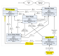
1. If you want the CAN message receipt to change the device from the sleep to normal mode, you will have to pass through Standby mode. Please reference the image I sent above of the state diagram. Keeping EN and nSTB always high will ignore the CAN bus and move to Normal mode automatically.
My recommendation is to connect VIO to EN and nSTB. That way when the device is in Sleep mode, it will enter Standby mode from a CAN wake message. Once in Standby, INH is high, triggering the MCU to set VIO high. Because VIO is connected to EN and nSTB, it will move from Standby to Normal mode.
2. Section 3 of the document below can help you pick a CMC. TCAN1043-Q1 can handle +/- 58V on the CANH/CANL bus so any part below the measured transient voltage will work. Specifically, Epcos B82789C0223 will work for your system.
https://www.ti.com/lit/an/slla271/slla271
Let me know if that helps or if you have any more questions.
Best,
Ethan
Hi Ethan,
we have made changes as suggested by you please review enclosed schematic and confirm
Vishnu,
This schematic looks good, although I noticed that the CMC is not placed. This might be intended, but I wanted to point this out. If you were to place it, it would go in between the transceiver and the termination resistors.
Additionally, I now noticed that the R1 and R2 termination resistors are DNF. Depending on the placement of the devices on the CAN bus, the two furthest end devices should have termination resistors. This ensures that the line is impedance matched at 60 Ohms. You might already be aware of this, but I wanted to highlight it. This thread details CAN termination well: e2e.ti.com/.../sn65hvd251-can-bus-termination
Best,
Ethan
Hi Ethan,
we done following modification in schematic
1. CMC added
2. pull down R10 added at Vio pin.
3. Pin 11 left float.
schematic enclosed please review and confirm 5732.TCAN1043-Q1 CIRCUIT.pdf
Vishnu,
These modifications looks good.
The only minor comment I have is about the R2/R3 resistors used for termination. There are two ways to terminate the node: standard and split termination (preferred for cleaner bus signals). Initially you had it setup for split termination where you had two 60 Ohm resistors split by a 100nF capacitor to ground. I would recommend adding that capacitor back in to add that extra filtering, or I would recommend placing one resistor that is 120 Ohms instead of two resistors to save on cost.
This document explains it in further detail: www.ti.com/.../SSZTB40
However, the design is still good as it currently stands.
Best,
Ethan