This thread has been locked.
If you have a related question, please click the "Ask a related question" button in the top right corner. The newly created question will be automatically linked to this question.
Tool/software:
Hello,
I have seen similar questions on the forum but I'm not sure I understand if this is possible or not.
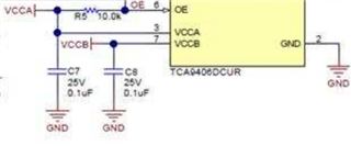
In our application, we have: VCCA = 2.5V and VCCB = 3.3V.
On power-up, VCCA goes up first and VCCB remains low down by default.
When necessary, the embedded processor enables VCCB (in order to communicate with the component on the B-side of the level-shifter).
From what I understand from the datasheet, OE must be tied to ground through a resistor until VCCB is powered-on, and only then OE can be set high to enable the device.
Since VCCA is the first voltage rail to be powered-on, OE cannot be tied directly to this rail.
Is it possible to tie OE to VCCB then?
We could also use the embedded processor to drive OE, but we want to minimize the I/O pin count in our system.
In the same design, we are also wondering if we can do the same thing for a TXS0108 (tell me if I'm wrong, but I understand that the TCA9406 is identical to the TXS0102).
Thank you for your help.
Maxime
Hi Maxime,
From what I understand from the datasheet, OE must be tied to ground through a resistor until VCCB is powered-on, and only then OE can be set high to enable the device.
Since VCCA is the first voltage rail to be powered-on, OE cannot be tied directly to this rail.
Is it possible to tie OE to VCCB then?
OE is referenced to VCCA, but is 5V tolerant according to the datasheet.
I see no issue with tying the OE pin to VCCB, but note that the OE VIH trigger will be based off the VCCA voltage, not VCCB voltage. It will trigger sooner than expected when tied to VCCB.
Now the datasheet does say to keep OE low until VCCA and VCCB are powered up. This is to ensure high-z on the i2c pins until VCCA and VCCB are powered up and ready.
Since the use of a GPIO is costly, we could try to implement this with a capacitor on OE.
The TCA9406EVM shows a 0.1uF cap to GND as a way to add RC to the OE so that OE powers up slightly before VCCA. I am assuming if applying this same design to VCCB, a capacitance >0.1uF will be required, or a weaker pull-up >10kohm.
Is there a specific timing requirement you are trying to achieve with OE?
I am not an expert on TXS0108, but I am assuming that the same thing can be achieved since TCA9406 architecture is closely related to the TXS family.
Scanning the TXS0108 datasheet, OE is still reference to VCCA, so I believe the same principle would apply to the TCA9406.
Regards,
Tyler
Hi Tyler,
Thank you for your quick answer.
Yes, I saw that it was 5V tolerant, which is why I was thinking of tying OE to VCCB (which will never go higher than 3.3V).
Regarding the timing requirement, we don't have one. The embedded processor will turn-on VCCA when ready and we can easily add a small delay (if necessary) before we start communicating via I2C, this is not a problem at all.
The only unknown timing is the time between VCCA and VCCB powering-up. This can be quite long in our case (> few seconds), which is why we have to keep OE low during this phase.
I will look at the RC in more details and get back to you if I have any further questions, but I suppose it could do the trick!
Best regards
Maxime
Hi Maxime,
Sounds good. I'll be looking forward to your reply.
I found a helpful tool on digikey. It is an RC time constant calculator that can be used to determine the rise-time.
Resistor-Capacitor (RC) Time Constant Calculator | DigiKey Electronics
Regards,
Tyler