This thread has been locked.

If you have a related question, please click the "Ask a related question" button in the top right corner. The newly created question will be automatically linked to this question.

DS90UB941AS-Q1: DS90UB941AS-Q1/DS90UB948-Q1 Schematic diagram

Part Number: DS90UB941AS-Q1

Tool/software:

TI-DS90UB948 原理图.pdfLBB_BBOX_MAIN_941原理图.pdf

Hello Expert,

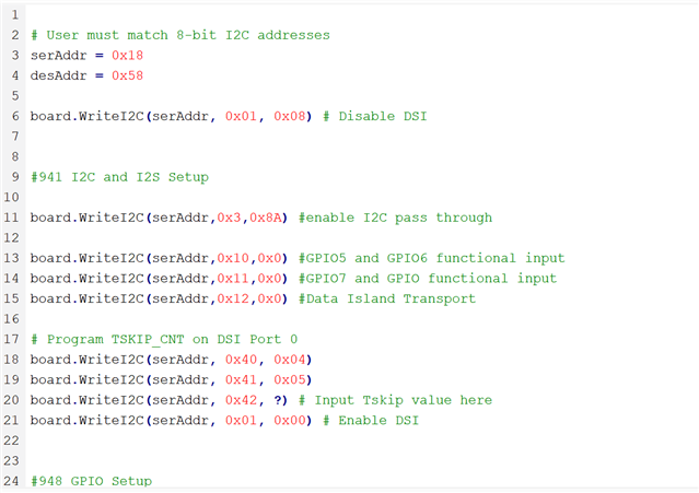
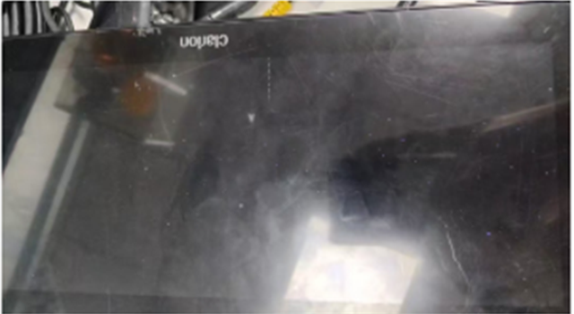
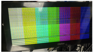
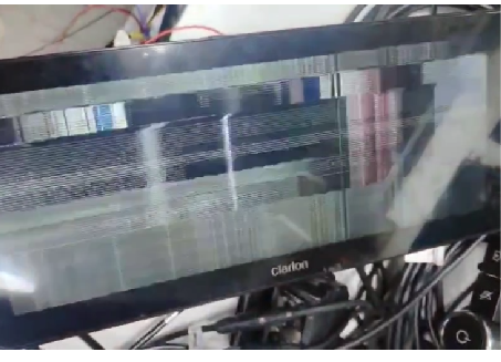
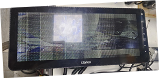
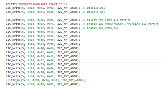
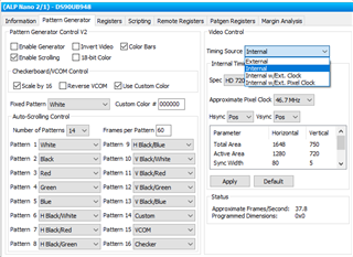
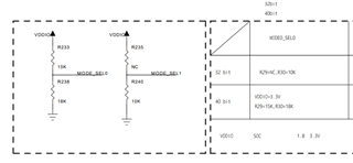
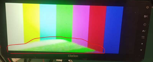
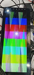
please help check our TI941/948 interface schematic. We encountered some anomalies during debugging and would like to confirm its accuracy.

Best Regards,

  • Hi,

    I'll review the schematic and get back to you with feedback by next Monday. In the meantime, please fill out the table below.

    OEM Name

    Tier1 Name

    Platform Name

    ??

    ??

    ??

    Best,

    Josh

  • HI Josh Baik

    OEM Name: Forvia, Tier1 Name: AUTOEQUIPS, Platform Name: Sigmastar SOC SSC8838G

    No.1 We encountered a black screen after using the driver configuration parameters you provided, as shown below.

    No.2 The link on the TI official website is similar to our usage scenario. Currently, we are using the configuration IC below. The output from the 941 is as follows: Test mode screen: Flickering black stripes.

    e2e.ti.com/.../ds90ub941as-q1-ub941-output-1920x720-color-and-resolution-abnormal

    No.3 The output video screen is shown in the following image.

    Could you please assist us? I would greatly appreciate your help.

  • Hi,

    It seems like you're asking about debugging rather than a schematic review request.

    To clarify, could you share the previous thread/history and the full script that we provided? Could you ping where you got the script? Additionally, it seems the script didn't update Tskip value. Please refer to the equation 14 on section 4.4 in the DSI Bring-up Application Note and input the value on 0x42. Furthermore, can you provide a register dump of the 941AS? 

    https://www.ti.com/lit/an/snla356/snla356.pdf?ts=1652812335521&ref_url=https%253A%252F%252Fwww.ti.com%252Fproduct%252FDS90UB941AS-Q1

    For no.2, has this ever happened when the 941AS uses the PATGEN with either the setting (internal timing and external clock) or (external timing and external clock)?

    Note that after a quick review of 941AS schematic, the MODE_SEL1 configuration is implemented as DSI inputs enabled / twisted pair / CLOCK from external osc.

    Best,

    Josh

  • HI Josh Baik

    1、Based on the response for this connection cable, we downloaded the driver configuration parameter file (941-948 example script). After using it, a driver black screen occurred (as shown below).

    DS90UB948-Q1: DS90UB948-Q1 /DS90UB941AS-Q1 Driver Code and Code Description Document support - Interface forum - Interface - TI E2E support forums

    2、The following link on the TI website describes a scenario that matches our current usage. We are currently using the IC with the configuration below. The output from the 941 is as follows:

    Test mode display: flickering black stripes appear.

    DS90UB941AS-Q1: UB941 output 1920x720 color and resolution abnormal - Interface forum - Interface - TI E2E support forums

    The following shows the internal clock self-test mode of the 941. Below are the register values and display screen; please help take a look.

    0 DSI input, 941 register values and display screen, using an external clock, 27MHz.

    DSI input, 941 register values, and initialization code for 941 and 948

    Could you please help me analyze which part might be causing the issue?

    Best Regards,

  • Hi,

    Thank you for the information, but please provide reg dump including indirect reg dump to check DSI error flag since DSI error is detected. If possible, please share the reg dump with text, not screenshot.

    Could you also share the display timing? I would like to double check about the DSI clock frequency since you put the value as 0x1E that indicates around 300MHz I guess.

    Have you ever checked the PATGEN with 948 only to verify the target timing and no system-level display-side issues? Have you tried with internal timing source? I would recommend the following steps for video control/timing source to see which factor would be issued:

    1. Deserializer PATGEN
      1. Internal - Internal timing source / Internal PCLK
      2. Internal timing source / External PCLK
      3. External - External timing source / External PCLK
    2. Serializer PATGEN
      1. Internal - Internal timing source / Internal PCLK
      2. Internal timing source / External PCLK
      3. External - External timing source / External PCLK

    Additional comment - One more thing during the 948 schematic review; 948 MODE_SEL0 is implemented pull-up 15k / pull-down 18k as below, but we don't have the configuration for MODE_SEL0. The reg 0x49 and typical voltage of 15k/18k with 3.3V are shown as MAP_SEL = H and Dual SWAP output. Please clarify if the configuration is correct.

    Best,

    Josh

  • 0X00:00
    0X01:00
    0X02:00
    0X03:08
    0X04:48
    0X05:53
    0X06:1e
    0X07:20
    0X08:03
    0X09:1e
    0X0a:0a
    0X0b:02
    0X0c:0a
    0X0d:02
    0X0e:03
    0X0f:1e
    0X10:0e
    0X11:21
    0X12:43
    0X13:65
    0X14:87
    0X15:a9
    0X16:cb
    0X17:ed
    0X18:0f
    0X19:00
    0X1a:01
    0X1b:00
    0X1c:00
    0X1d:00
    0X1e:00
    0X1f:00
    0X20:00
    0X21:00
    0X22:00
    0X23:00
    0X24:00
    0X25:00
    0X26:00
    0X27:00
    0X28:00
    0X29:00
    0X2a:00
    0X2b:00
    0X2c:00
    0X2d:00
    0X2e:00
    0X2f:00
    0X30:00
    0X31:00
    0X32:00
    0X33:00
    0X34:00
    0X35:00
    0X36:00
    0X37:00
    0X38:00
    0X39:00
    0X3a:00
    0X3b:00
    0X3c:00
    0X3d:00
    0X3e:00
    0X3f:00
    
    m_wPanelHSyncWidth = 8;
    m_wPanelHSyncBackPorch = 12;
    m_wPanelVSyncWidth = 7;
    m_wPanelVBackPorch = 8;
    m_wPanelHStart = 20;
    m_wPanelVStart = 15;
    m_wPanelWidth = 1920;
    m_wPanelHeight = 720;
    
    m_wPanelHTotal = 1984;
    m_wPanelVTotal = 792;
    m_wPanelDCLK = 95 MHz;
    
    
    m_wHactive = 1920;
    m_wHpw = 8;
    m_wHbp = 12;
    m_wHfp = 44;
    m_wVactive = 720;
    m_wVpw = 7;
    m_wVbp = 8;
    m_wVfp = 57;
    m_wFps = 60;
    
    58  04  00  f0  fe  1e  00  18  00  00  00  00  00  00  00  00
     00  00  00  00  00  00  00  00  00  01  00  00  23  10  00  00
     00  00  40  34  08  00  83  84  01  00  00  00  00  00  00  00
     00  00  90  25  01  00  00  ed  00  00  00  03  20  e0  23  00
     43  03  03  00  60  88  00  00  0f  81  00  08  00  00  63  00
     03  10  00  01  80  00  00  00  00  7f  20  20  00  00  00  00
     00  00  00  00  00  04  0e  00  00  00  00  00  00  00  00  00
     00  00  00  07  07  08  00  00  00  00  00  00  02  00  00  00
     00  00  00  00  00  00  00  00  00  00  00  00  00  00  00  00
     00  00  00  00  00  00  00  00  00  00  00  00  00  00  00  00
     00  00  8c  00  00  00  00  00  00  00  00  00  00  00  00  00
     00  00  00  00  00  00  00  00  00  00  00  00  00  00  00  00
     00  00  00  00  00  00  00  00  c0  00  00  00  00  00  00  00
     00  00  00  00  00  00  00  00  00  00  00  00  00  00  00  00
     00  00  00  00  00  00  00  00  00  00  00  00  00  00  00  00
    5f  55  42  39  34  38  00  00  00  00  00  00  00  00  00  00
    
    0X01:00
    0X02:00
    0X03:1d
    0X04:14
    0X05:1e
    0X06:00
    0X07:00
    0X08:00
    0X09:00
    0X0a:00
    0X0b:00
    0X0c:00
    0X0d:00
    0X0e:00
    0X0f:5f
    0X10:00
    0X11:00
    0X12:00
    0X13:00
    0X14:00
    0X15:01
    0X16:00
    0X17:00
    0X18:00
    0X19:00
    0X1a:00
    0X1b:00
    0X1c:00
    0X1d:00
    0X1e:00
    0X1f:00
    0X20:7f
    0X21:00
    0X22:ff
    0X23:7f
    0X24:00
    0X25:00
    0X26:00
    0X27:00
    0X28:00
    0X29:00
    0X2a:3e
    0X2b:00
    0X2c:00
    0X2d:00
    0X2e:00
    0X2f:00
    0X30:00
    0X31:20
    0X32:00
    0X33:04
    0X34:00
    0X35:20
    0X36:00
    0X37:00
    0X38:00
    0X39:00
    0X3a:02
    0X3b:03
    0X3c:00
    
    18  00  00  fa  00  00  58  00  00  01  06  00  47  30  00  00
     00  00  00  db  00  00  fe  5e  7f  7f  01  00  e0  01  01  00
     0b  00  25  00  00  00  00  00  01  20  20  a0  00  00  a5  5a
     00  b9  80  07  0c  00  00  00  00  00  00  00  00  00  81  02
     04  05  1e  00  00  00  00  00  00  00  00  00  00  00  00  0c
     16  00  00  00  00  00  00  02  00  00  d9  00  07  06  44  5f
     22  02  00  00  10  00  00  00  00  00  00  00  00  00  20  00
     00  00  00  00  00  00  00  00  00  00  00  00  00  00  7c  00
     00  00  00  00  00  00  00  00  00  00  00  00  00  00  00  00
     00  00  00  00  00  00  00  00  00  00  00  00  00  00  00  00
     00  00  00  00  00  00  00  00  00  00  00  00  00  00  00  00
     00  00  00  00  00  00  00  00  00  00  00  00  00  00  00  00
     00  00  82  00  38  00  00  64  40  00  00  00  00  02  ff  00
     00  00  00  00  00  00  00  00  00  00  00  00  00  00  00  00
     00  00  82  00  28  08  00  00  00  00  00  00  00  02  00  00
     5f  55  42  39  34  31  00  00  00  00  00  00  00  00  00  00 
    

    Dear 

    Attached is the indirect register dump we promised to provide.

    We could not confirm. As shown in the figure, we used the 948 to check PATGEN solely to verify the target timing, but an issue occurred on the display side.

    pixel clock  85 M  HTotal = 1940; VTotal = 735;
    active = 1920;
    Vactive = 720;
    HSyncWidth = 8;
    HSyncBackPorch = 12;
    VSyncWidth = 7;
    VBackPorch = 8;
    HStart = 20;
    VStart = 15;

    This is the resistor that 948 currently MODE_SEL [1:0] attached. The data has been grabbed out with text, please help confirm whether there is a possibility of instability in the 948 data?

    Best,

  • Hi,

    Since the PATGEN with 948 only is not working properly, we first need to verify the target timing and no system level on display side. What timing control did you select when checking PATGEN with 948 only? We can narrow down to what factor to issue, such as internal/external timing sources or internal/external PCLK.

    Also, please double-check the display timing. The parameters below you mentioned and video_timing.txt do not match total parameters and PCLK.

    pixel clock  85 M  HTotal = 1940; VTotal = 735;
    active = 1920;
    Vactive = 720;
    HSyncWidth = 8;
    HSyncBackPorch = 12;
    VSyncWidth = 7;
    VBackPorch = 8;
    HStart = 20;
    VStart = 15;

    Best,

    Josh

  • Hi,

    There were some errors in the previous description. I update the latest status now. 948 PATGEN is normal, and  941 PATGEN use internal clock is also normal. 941 PATGEN use external clock have some issues (have stripes). We hope to receive guidance on resolving abnormal stripes.thanks !

    941 reg dump 

    18 00 00 ea 00 00 58 00 00 01 16 00 07 30 00 00
    00 00 00 db 00 00 fe 5e 7f 7f 01 00 e0 01 01 00
    0b 00 25 00 00 00 00 00 01 20 20 a0 00 00 a5 5a
    00 b9 80 07 0c 00 00 00 00 00 00 00 00 00 81 02
    04 05 10 00 00 00 00 00 00 00 00 00 00 00 00 8c
    16 00 00 00 00 00 00 02 00 00 d9 00 07 06 44 43
    22 02 00 00 17 00 00 00 00 00 00 00 00 00 20 00
    00 00 00 00 00 00 00 00 00 00 00 00 00 00 7f 00
    00 00 00 00 00 00 00 00 00 00 00 00 00 00 00 00
    00 00 00 00 00 00 00 00 00 00 00 00 00 00 00 00
    00 00 00 00 00 00 00 00 00 00 00 00 00 00 00 00
    00 00 00 00 00 00 00 00 00 00 00 00 00 00 00 00
    00 00 82 00 38 00 00 64 40 00 00 00 00 02 ff 00
    00 00 00 00 00 00 00 00 00 00 00 00 00 00 00 00
    00 00 82 00 28 08 00 00 00 00 00 00 00 02 00 00
    5f 55 42 39 34 31 00 00 00 00 00 00 00 00 00 00

    948 reg dump 

    58 04 00 f0 fe 1e 80 18 00 00 00 00 00 00 00 00
    00 00 00 00 00 00 00 00 00 01 00 00 23 10 00 00
    00 00 40 20 08 00 83 84 01 00 00 00 00 00 00 00
    00 00 90 25 01 00 00 8e 00 00 00 00 20 e0 23 00
    43 03 03 00 60 88 00 00 0f 81 00 03 00 00 63 00
    03 10 00 01 80 00 00 00 00 7f 20 20 00 00 00 00
    00 00 00 00 00 04 0e 00 00 00 00 00 00 00 00 00
    00 00 00 07 07 08 00 00 00 00 00 00 02 00 00 00
    00 00 00 00 00 00 00 00 00 00 00 00 00 00 00 00
    00 00 00 00 00 00 00 00 00 00 00 00 00 00 00 00
    00 00 8c 00 00 00 00 00 00 00 00 00 00 00 00 00
    00 00 00 00 00 00 00 00 00 00 00 00 00 00 00 00
    00 00 00 00 00 00 00 00 c0 00 00 00 00 00 00 00
    00 00 00 00 00 00 00 00 00 00 00 00 00 00 00 00
    00 00 00 00 00 00 00 00 00 00 00 00 00 00 00 00
    5f 55 42 39 34 38 00 00 00 00 00 00 00 00 00 00

    941 Dump register

    0X01:00
    0X02:00
    0X03:1d
    0X04:14
    0X05:10
    0X06:00
    0X07:00
    0X08:00
    0X09:00
    0X0a:00
    0X0b:00
    0X0c:00
    0X0d:00
    0X0e:00
    0X0f:1f
    0X10:00
    0X11:00
    0X12:00
    0X13:00
    0X14:00
    0X15:00
    0X16:00
    0X17:00
    0X18:00
    0X19:00
    0X1a:00
    0X1b:00
    0X1c:00
    0X1d:00
    0X1e:00
    0X1f:00
    0X20:7f
    0X21:00
    0X22:ff
    0X23:7f
    0X24:00
    0X25:00
    0X26:00
    0X27:00
    0X28:00
    0X29:00
    0X2a:3e
    0X2b:00
    0X2c:00
    0X2d:00
    0X2e:00
    0X2f:00
    0X30:00
    0X31:20
    0X32:00
    0X33:04
    0X34:00
    0X35:20
    0X36:00
    0X37:00
    0X38:00
    0X39:00
    0X3a:02
    0X3b:03
    0X3c:00

  • Hi,

    The issue with external clock is indicated about discontinuous DSI clock and clock requirements as following the flow chart in app note. Please see section 4.1 in app note.

    Note that the external clock should be the same frequency as the PCLK. As per the DS90UB941AS datasheet, the external clock should be programmed to be the same frequency as the PCLK.

    Could you clarify again what the format/frequency of your DSI input to the 941AS is?

    • What video mode is the SoC operating in (burst mode, non-burst mode with sync pulses, or non-burst mode with sync events)?
    • What clock mode is the SoC DSI clock set (continuous mode or non-continuous mode)?
    • What is the DSI rate and what is the PCLK (85 MHz or 95 MHz)?

    Best,

    Josh

  • Hi,

    we use video mode is sync pulses   .RGB888 ;

     DSI clock is continuous mode;

    DSI rate is 1984*792*60*24/4/2=282.8M

    PCLK is 1984*792*60=94.3M

    The data we obtained at the 948 output is different from what we set at SOC:

    getfor948

    fm_value:32914

    lvds_clk_in:32914

    Port B lvds clock:

    fm_value:32914

    lvds_clk_in:32914

    sync_polarity = F

    LT9211_VideoCheck

    hfp: 2172

    hs: 1

    hbp: 14

    hact: 1920

    htotal:9

    vfp: 89

    vs: 7

    vbp: 24

    vact: 720

    vtotal: 1864

    SOC set


    m_wHactive = 1920;
    m_wHpw = 8;
    m_wHbp = 12;
    m_wHfp = 44;
    m_wVactive = 720;
    m_wVpw = 7;
    m_wVbp = 8;
    m_wVfp = 57;
    m_wFps = 60;
    HTotal = 1984;
    VTotal = 792;

    Is this a problem with setting up registers for 941 or 948?or SOC output timing is error ?

    Best,

  • Hi Josh

    The log above is about the output of 948 is We tested the logs of 42 frames,Now I am re uploading 60 frames of the log。

    Port A lvds clock:

    fm_value:47079

    lvds_clk_in:47079


    Port B lvds clock:

    fm_value:47080

    lvds_clk_in:47080


    sync_polarity = F
    LT9211_VideoCheck


    hfp: 2170
    hs: 1
    hbp: 21
    hact: 1920
    htotal:2
    vfp: 89

    vs: 7
    vbp: 24
    vact: 720
    vtotal: 1824

  • Hi,

    Based on the PCLK (94.3MHz) and DSI clock frequency (282.8MGbps), the incorrect TSKIP_CNT value was programmed as 0x1E.

    • f_DSI = 0.2828 GHz
    • TSKIP_CNT = Round (65*f_DSI-5) = 13 which means you need to program 0x1A to indirect register 0x05, not 0x1E.

    Best,

    Josh

  • Hi Josh

    0x42 set 0x1A
    We will conduct an experiment tomorrow,and i have a question 。

    We measured that the value of 948 is PASS=0:, indicating that an error has occurred now. Which part caused this error?

  • Hi,

    The datasheet you refer to is an old version. The new datasheet gives the correct description for PASS on 948. Note that it is not used during normal mode, so PASS = 0 is the expected behavior.

    Best,

    Josh

  • Hi Josh

      I program 0x1A to indirect register 0x05,is Same ending。Do you have the same usage example configuration as us?

    Can you help us review the hardware again?

    Thanks

    6153.pdf
    948(1).pdf

    Best

  • Hi,

    I have reviewed the schematic and have some feedback. Since you selected External Reference Clock Mode on MODE_SEL1 (#4), you need to match the frequency with the desired DSI clock, not 27MHz for the external clock as you mentioned above, and it is not clarified the OSC spec in the schematic. Please see the requirements in the app note.

    Best,

    Josh

  • Hi Josh

      our DSI clock is 0.2828Ghz ,Pclk is 94.3M .so Should the external clock be set to 94.3MHz ?

    Best

  • Hi Masami,

    External Reference Clock Mode utilizes an external clock on the REFCLK0 or REFCLK1, and it is recommended that this be matched to the DSI PCLK. This also follows the equation described below.
    I recommend seeing the app note I shared above. It will guide the consideration of the DSI source configuration and the implementation of a solution with 941AS.

    Best,

    Josh

  • Hi Josh

    We have chosen a suitable external crystal oscillator、BRIDGE_CFG2[1:0] Reg is set External Reference Clock Mode. But now it's consistent with choosing

    DSI Reference Clock Mode。If we choose DSI Reference Clock Mode。 Except for the indirect register 0x05 and set  dsi is  DSI_CONTINUOUS_CLOCK ,Do we need to configure other registers for clk?

    Best

  • Hi,

    I will get back to you with the feedback within 1-2 business days.

    Best,

    Josh

  • Hi,

    Have you checked if it is enabled PATGEN with internal timing and an external clock from 941AS?

    DSI Reference Clock Mode。If we choose DSI Reference Clock Mode。 Except for the indirect register 0x05 and set  dsi is  DSI_CONTINUOUS_CLOCK ,Do we need to configure other registers for clk?

    The following options may be configured for each port:

    • DSI_CONTINUOUS_CLK – register 0x4F[7]
    • DSI_LANES – register 0x4F[3:2]
    • DSI_BYTES_PER_PIXEL – register 0x54[5:4]
    • BRIDGE_CLK_MODE – register 0x56[1:0]
    • FREQ_STBL_THR – register 0x5C[4:3]
    • FREQ_HYST – register 0x5C[2:0]
    • PatternGen direct and indirect registers – 0x64-0x69
    • DPHY and DSI configurations via DSI indirect register page

    At this time, I recommend you follow the bring-up flow in the app note step by step to check the establishment properly.

    Best,

    Josh

  • Hi, Josh Baik 

       We have tested all the registers mentioned above, but the stripes still exist。Is it possible that this is a hardware issue?

    Best

  • Hi,

    Have you checked if it is enabled PATGEN with internal timing and an external clock from 941AS?

    I don't think the register configuration is a priority at this point. Before further investigation about the hardware issue, please confirm if you followed the bring-up flow chart since the above question has not been answered.

    Best,

    Josh

  • hi Josh

     I use PATGEN with internal timing and an external clock from 941AS,Also has stripes。

    Best,