This thread has been locked.

If you have a related question, please click the "Ask a related question" button in the top right corner. The newly created question will be automatically linked to this question.

DP83848-EP: The cause of the attenuation of RX signal amplitude

Part Number: DP83848-EP

Tool/software:

Hi Hillman,

Thank you for your reply.
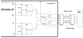
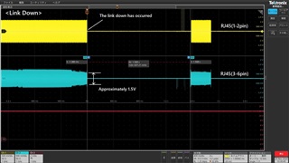
We will attach the waveform and circuit diagram.
We are having a lot of trouble with link-downs in LAN communication with the components we use in our products.
We think that the cause of the link-downs is that the amplitude of the RJ45 (3,6pin) is decreasing.
The transceiver used in the component is the DP83848-EP.
We want to monitor the waveform inside the component directly, but this was not possible due to the structure of the component.
Therefore, we monitored the RJ45 as shown in the attached file.
What could be the cause of the decrease in amplitude of the RJ45 (3,6pin) in this way?
(Power supply of the transceiver IC, connection of signal lines, design of artwork, etc.)
Could you give us some advice?

Best regards,
Tsuji

  • Hi Tsuji, 

    Thank you for the information. I wanted to clarify a few more things in order to help with the debug

    Would you be able to provide a schematic of your design with the DP83848? 

    What link speed was the board using at the time these waveforms were taken?

    Best,

    Vivaan

  • Hi Vivaan,
    Thank you for your reply.
    As this component is a purchased item, there is no circuit diagram.
    I created the LAN interface circuit by referring to the web documents and PWB.
    The link speed is 100base-Tx.
    In addition, the Auto MDI/MDI-X on the PC side is turned off using software.
    I look forward to you advice.

    Best regards,
    Tsuji

  • Hi Tsuji,

    I am having a little trouble understanding your setup. I thought that you were using the DP83848 chip in your own design. Are you using one of the evaluation boards we have on TI.com for the DP83848, such as the ones in the link below?

    https://www.ti.com/product/DP83848-EP#hardware-development 

    LAN interface circuit by referring to the web documents

    Is this referring to the circuitry around the MDI lines you are probing for the waveforms? This is what I wanted to take a look at, if you have a schematic available of your design. 

    Any reason for disabling the auto MDIX on the PC?

    Best,

    Vivaan

  • HI Vivaan,
    Thank you for your reply.

    I'm sorry for confusing you.
    The DP83848 chip is used in the PCB of the our products. 
    I'm not using the TI evaluation board for the DP83848.

    We don't have the PCB's circuit diagram.
    (But we have the PCB)
    The attached circuit diagram is what I reverse-engineered from the PCB.

    These waveforms were measured on the MDI line.

    By disabling AmutoMDI/MDI-X on the PC,
    I think it is possible to identify the TX and RX signals on the MDI line.

    Best regards,
    Tsuji

  • Hi Tsuji,

    There are a number of things that could be causing this issue. Unfortunately, We would need the circuit diagram to make sure that some of the hardware requirements for proper functioning of the PHY are met. 

    While we do need the schematic, one possible reason could be the instability of the VDDIO voltage, which directly drives the TD pins. This is a possible reason for this issue, but to debug more, a schematic would be necessary. 

    Best,

    Vivaan

  • Hi Vivaan,

    Thank you for your reply.

    We are sorry that we cannot provide you with a circuit diagram.
    You are referring to VDDIO as IOVDD33 (32pin and 48pin).
    We will check this on the PCB.

    We very much appreciate your reply.

    Best regards,
    Tsuji

  • Hi Tsuji, 

    Unfortunately, a schematic would be required for a proper debug, but here are some possible causes that you may be able to look into as well. 

    • Verify that the magnetics used on the PCB meet the specifications laid out in the datasheet
    • Verify that the center taps are connected to VDD
    • Verify the ripple on IOVDD33
    • Verify that the correct decoupling capacitors are used in the MDI circuit in the differential pairs

    These are a few possible causes off the top of my head, but if you are able to find the schematic and are still having this issue, I will be happy to help debug more. 

    Best,

    Vivaan