This thread has been locked.

If you have a related question, please click the "Ask a related question" button in the top right corner. The newly created question will be automatically linked to this question.

DP83867IR: DP83867 Compliance test Fail

Part Number: DP83867IR

Tool/software:

Hi Expert,

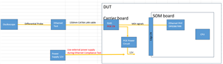
Our customer is currently doing Ethernet Compliance testing and has had some failures
We are referring to the following application note:
https://www.ti.com/lit/an/snla239c/snla239c.pdf

Failures:

10base:
- MAU Int: The signal level is small, so the mask hits and it fails
- MAU Int Inverted: The signal level is small, so the mask hits and it fails
- Differential Voltage: The signal level is small, so it fails

100base : All items are Passed
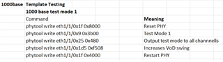
1000base
- Template Test Point F: The rising part of the signal waveform is hit by the mask
- Template Test Point H: The falling part of the signal waveform is hit by the mask

Question:

Q1: 10base: Are there any setting commands/registers to increase the signal level?

Q2: 1000base: Are there any commands/registers to adjust the Rise/Fall of the signal waveform?

Please refer to the attached excel file.

Thanks,
Huy

Ethernet_Compliance_Test_Fail.xlsx

  • Hello Huy,

    Can you please provide the register commands used to run these tests?

    Can you also please evaluate the design against our schematic and layout checklists to rule out any board design contributions to the tests?

    Sincerely,

    Gerome

  • Hi Gerome,

    - The register commands used to run these tests (According to application note snla239c)

      + 10base
             Command                                           Meaning
             phytool write eth1/1/0x1f 0x8000        Reset PHY
             phytool write eth1/1/0x0 0x100           Programs DUT to 10Base-Te Mode
            phytool write eth1/1/0x10 0x5008        Programs DUT to Forced MDI or MDIX mode (0x5028)
            phytool write eth1/1/0x16 0xd004        Programs DUT to generate traffic
            phytool write eth1/1/0x1f 0x4000         Restart PHY

     + 1000base


    Both waveform and detailed test information I have attached as "Ethernet_Compliance_Test_Fail.xlsx" file, can you open it?

    -About "schematic and layout checklists" I will check with our customers and respond as soon as possible

    Thanks,
    Huy

  • Hi Huy,

    I would like to wait on the completion of the schematic and layout checklist before providing altering registers for 10Base-Te.

    However, for 1G Mask, please consult this FAQ:

    https://e2e.ti.com/support/interface-group/interface/f/interface-forum/1367619/faq-dp83867e-1000base-t-ethernet-compliance-register-script

    Can you also please provide picture of the setup? I am particularly interested in the cable and probe board.

    Sincerely,

    Gerome

  • Hi Gerome,

    I am attaching the 2 checklist files you requested, please check it.

    + The commands for 1G under Rev B, we have seen and are testing them.

    picture of the setup: -> I will ask our customer to provide, please wait a moment.

    Thanks,

    Huy
    SLVRBN1A-Schematic_check.xlsx

    SNLR048A_Layout_check.xlsx

  • Hi Huy,

    While schematic may look good, it appears that a primary culprit for the low amplitude would be the long trace lengths on MDI (~5" in total with interconnect). It would be advised to see if there are any ways to optimize this to bring within 3". In addition, length matching is also important to ensure proper signal integrity.

    Sincerely,

    Gerome

  • Hi Gerome,

    Thank you for confirming the checklist

    Regarding the MDI line length (<3inch), we will consider it. But it is difficult to satisfy when the structure is SOM + Carrier (wide Carrier).

    Is there a register that can adjust the amplitude of the signal?

    *I would like to send you a picture of the setup. (Excel File)

     Thanks,
    Huy

    EtherTest_picture.xlsx

  • Hi Gerome,

    currently we can't modify PCB,
    is there any register that can be adjusted?

    Thanks

    Huy

  • Hi Huy,

    Reg 0xA0 and 0xA1 can help in adjusting signal amplitude per channel. Please experiment with these fields accordingly to see if they help in these tests.

    Sincerely,

    Gerome

  • Hi Gerome,

    Thanks for your feedback

    But since these 2 registers are not listed in the datasheet, can you tell me the range of values ​​that can be set?

    We will try with some values

    Thanks,

    Huy

  • Hello,

    Please refer to the latest datasheet as those registers are included.

    Sincerely,

    Gerome

  • Hi Gerome,

    I apologize for the late response.

    ■ By adding the 1000base Rise/Fall adjustment command/register,
    phytool write eth1/1/0x0000 0x0140
    phytool write eth1/1/0x0010 0x5008
    the waveform became slightly rounded and the mask hit was no longer made, but it still managed to pass the mask just barely.

    ■ A compliance test was performed at 1000BASE-T.
    we adjusted the register (0xA0, 0xA1) that you told me about (this register appears to be common to 10BASE-TE/100BASE-T/1000BASE-T).
    The settings immediately after boot and immediately after executing the test mode switching command were x0000 = -16% change in gain for channels A/B/C/D, and since the signal amplitude was insufficient to perform a compliance test, we made the following settings and ran it.
    chA : x1001 = +2% change in gain
    chB : x1001 = +2% change in gain
    chC : x1011 = +8% change in gain
    chD : x1000 = 0%( No change in gain)
    Channel C requires a significantly larger gain setting than the other channels. I tried using two boards, but got the same results.
    Even if the gain setting was made smaller, there was no tendency for there to be any margin for mask hits.

    Can you help me answer the questions below?

    Q1:Why does chC need to be set to a larger value than the others? Does the device itself have that characteristic? Or is there another new setting address?

    Q2: I still feel like I need a little more margin for mask hits.
    Are there any (unreleased?) commands/Register that allow me to adjust the emphasis of the Tx output signal on DP83867IR?

    Q3: Based on the results of this compliance test, we are planning to reflect the gain setting values ​​for each channel in the firmware. However, this relates to Q1, but due to differences in DP83867IR lots, we need to confirm whether it is okay to adjust the gain at a fixed value on the board.
    With the DP83867IR, to what extent is the actual Tx output amplitude level variation guaranteed depending on the gain setting?

    P/S: Although there is a Japanese part, I will send you the 1000base Test results.20241211-Ethernet-ComplianceTest-Result.xlsx
    Thanks,
    Huy

  • Hi Huy,

    Regarding your questions:

    1) It may be that Channel C's routing maybe impacting the performance compared to channels A, B, and D. 

    2) We do not have any more unreleased register commands to assist with signal strengthening. However, Reg 0xA2/A3 may help. Increasing per channel has been correlated with increased peak voltage.

    3) Reg 0xA0, and Reg 0xA1 are trim value registers. These will vary part to part. It is important to understand what is the default value for that part and adjust accordingly.

    Sincerely,

    Gerome

  • Hi Gerome,

    Thanks for your reply


    Q1&Q3: Does it mean there is no difference between production lots? And this register adjustment depends on each PCB


    Q2: I got it, I will try it

    Thanks,
    Huy

  • Hi Huy,

    Q1,3: All parts are expected to be within specification of datasheet. However, as PCB would add parasitic to signaling, it is possible that adjustment will need to be made.

    Sincerely,

    Gerome