This thread has been locked.

If you have a related question, please click the "Ask a related question" button in the top right corner. The newly created question will be automatically linked to this question.

TUSB1002A: USB3.0

Part Number: TUSB1002A

Tool/software:

Hi Team,

We are implementing Type-C 3.0 connectors in a one-to-one configuration for our board. One end of the board connects to a PC using a Type-A to Type-C cable, while the other end interfaces with another Type-C connector.

Could you please advise on the appropriate CC1 and CC2 pin configurations for all three connection points? I’ve attached the schematic for your review and would appreciate any suggestions to optimize the design.

Looking forward to your feedback.

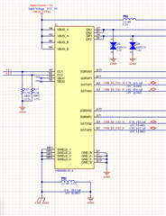
review the schematic and suggest me a solution. attached schematic below:

Connectors on the first board:

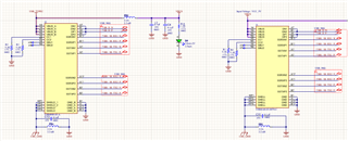
connector on the second board:

  • Hi,

    Are you using a Type-C receptacle on both sides of your first board? Type-C receptacle to Type-C receptacle is not a supported application for our parts nor is it defined in the USB-C spec. The issue is that you cannot pass the CC lines directly from one Type-C port to another or the correct CC line may not pass through.

    You need a CC (or PD) controller on each type-C port to negotiate orientation, role, and current mode.

    The way you currently implement the SSRX/TX lines would also struggle to find the correct orientation. Based on the CC line used (1 or 2) the TX1/RX1 or TX2/RX2 will be used for USB3 communication. Since you are pulling down the CC lines on both type-C receptacles, the orientation will not be passed through from the upstream to downstream recpetacles.

    Best,

    Shane