This thread has been locked.

If you have a related question, please click the "Ask a related question" button in the top right corner. The newly created question will be automatically linked to this question.

TCA9539-Q1: The rising or falling edge slew rate rang of the port inputs in the input mode to generate an interrupt at INT pin

Part Number: TCA9539-Q1
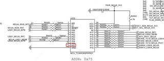
Other Parts Discussed in Thread: TCA9539

Tool/software:

HI BU team 

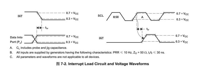
In the datasheet  an interrupt is generated by any rising or falling edge of the port inputs in input mode (PIN11). My customer wanted to the rising or falling edge slew rate rang for PIN11 in input mode. 

Customer doesn't find this requirement in the datasheet. Would you hep share it?

Thanks 

  • Hi Ted,

    Pin 11 is P07, when configured in the input mode is a high-z input. The rising / falling edge is generated externally, this is why there is no datasheet spec for this scenario.

    The slew rate is dependent on the customers external driver. 

    Regards,

    TYler

  • HI Tyler

    Thanks for your quick reply. 

    But what's the conditions or threshold to make TCA9539 to generate a interrupt at INT pin ? The decision conditions pulling INT low should be controlled by TCA9539-Q1. 

    Thanks   

  • Hi Ted, 

    An interrupt is generated on /INT when a Pxx pin changes from its original state. I.e., if P10 was originally pulled HIGH, and P10 is a high-Z input, pulling LOW on P10 would trigger an interrupt on /INT. 

    This is the same for all Pxx pins configured as inputs through the configuration register of the device. 

    Regards,

    Tyler

  • HI Tyler

    If what your said is true, would you help share your comments on my customer's findings? 

    Below is the schematic as reference where TCA9539-Q1 is powered by 3.3V power supply and p10 is floated. 

    Customer touched the p10 pin with an tweezers for a while then measure the waveform with an scope. The generated noise waveform can been found in below screenshot. During the test, the operator wore the antistatic gloves. 

    The measured VIH are less than 3.3*0.7=2.31V but the readback are changed and the interrupts are also generated.

    The background is that the floating p10 pin triggered  many interrupts in the released to markets car. So far 1pcs was reported and customer is doing the investigation. 

    Thanks 

  • When you allow an input pin to float, it can indeed oscillate (in addition to shoot-through currents and possible damage; see [FAQ] How does a slow or floating input affect a CMOS device?)

    Add a pull-up or pull-down resistor, or configure the pin as output.

  • Hi Ted,

    Please see Clemens comments. He summed it up with floating CMOS pins. This is what I would expect the IO expander to do if you conducted this type of testing. 

    Regards,

    Tyler

  • HI Clemens, Tyler

    Thanks for your comments and sharing. 

    Suggest BU to update the datasheet and note that the unused pins should be pulled-up or pulled-down via resistor in the pin definitions. Customer doesn't find the suggestion on the unused pins . 

  • Hi Ted,

    Note taken. This is probably something we can add to the description of the datasheet so that customers can decide whether they want to tie floating inputs high or low, or set the pin as a floating output. 

    Regards,

    Tyler