This thread has been locked.
If you have a related question, please click the "Ask a related question" button in the top right corner. The newly created question will be automatically linked to this question.
Tool/software:
Dear TI support team,
I use your THVD1424 for a New Space MRO Project.
I use it in full-duplex, therefore the satellite customer load will be about 100 Ohms, even 120 Ohms as it is point to point connection, only one receiver is interfaced with it.
I have to describe my interface to the customer. Driver spec gives differential output voltage for a VCC of 5V. My VCC is only 3V3, so what would be the minimal and typical differential output voltage on a 100 Ohms (or 120 Ohms) load resistor ?
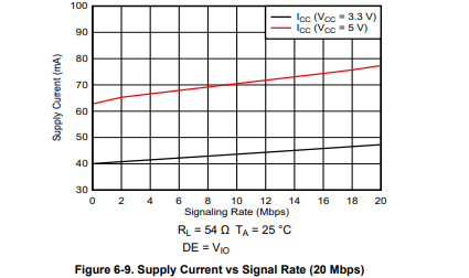
Also, how would you calculate the power dissipation in regard of datarate ? I couldn't find any Cpd or any way to calculate it in the datasheet.
I precise that I do not use on-chip termination resistor to avoid further self heating of the component.
I thank you in advance for your support.
Regards,
Cédric
Hi Cédric
Having a differential load of 100 Ohms is shown in datasheet - the minimum is 2V that is for the full VCC supply range from 3V to 5.5V - the typical is only for VCC = 5V and is not a guaranteed value - we don't spec 3.3V typical condition - I'd estimate around 2.7V typically but that is not a guarantee - the only thing I can guarantee for sure is that it will hit at least 2V across recommended operational range with a load of 100 ohms between differential I/O.
There is no direct way to calculate power dissipation for this device - the best we have is a supply current versus signaling rate graph that can be used as a guide but it doesn't match your application directly:
This graph shows typical RS-485 load at room temperature - the larger load resistance will result in less supply current but if your application is running at higher than room temperature operation you could see higher current than shown. Essentially this a starting point - but ultimately there a lot of factors that impact supply current so testing in specific system is the only sure fire way to get an accurate measurement for your specific application. From the graph you can estimate a Cpd value of about 1.5nF at max data rate and around 12.5nF at lower data rates where data rate is 2 * switching frequency - that isn't a guaranteed value - but can serve as an estimation - just so that is clear how I got those numbers:
At 3.3V at 20Mbps that gives an ICC of about 48mA which gives a power of 158.4mW - where power can also equal P = Cpd * VCC^2 * Fsw * N; VCC = 3.3V, Fsw = data_rate/2, N = 1 - solve for Cpd and you get right around 1.5nF - but if you calculate at it at lower data rates such as 2Mbps you are looking at around 12.5nF - and it should be noted that the DC current is essentially just the load current out of the differential driver as the quiescent current is a small part of total supply current when transmitting - so the higher load will also impact this current same as temperature. So these are very rough estimations and this needs to be measured in actual system for best accuracy.
Best,
Parker Dodson
Hi Parker,
Thank you very much, this is a very nice answer to me, and I do agree that the best way to process the power dissipation would be to test it.
I did use previously your THVD9491 and indeed the differential output voltage was always between 2 and 3V.
Minimum of 2V is fine for me, typical will be somewhere betwen 2 and Vcc (3V3), which is also fine for me.
Thanks for the quality of your answer.
Regards,
Cédric