This thread has been locked.

If you have a related question, please click the "Ask a related question" button in the top right corner. The newly created question will be automatically linked to this question.

TCAN1043-Q1: TCAN1043 wake up

Part Number: TCAN1043-Q1
Other Parts Discussed in Thread: TCAN1043,

Tool/software:

Hi Ti team,

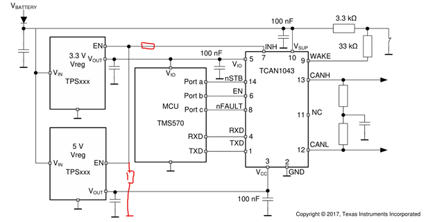
Our actual application is similar to the recommended application below, but with the addition of a divider resistance between the INH and DC-DC EN pins.

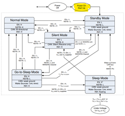
The normal working voltage of Vbattery is 12V. When the Vbattery voltage drops to 5V: VEN < VEN-L, the DCDC is turned off. VCC < UVvcc, VIO < UVvio, Vsup > UVsup, TCAN1043 is in a sleeping state. When the Vbattery voltage is restored to 12V, the TCAN1043 has been in sleep mode due to undervoltage. The INH pin voltage is 0V, which causes the system to fail to power up and system functions cannot be restored.
1. In this case, is there any other way to wake up apart from using CAN BUS?
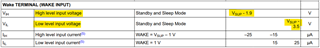
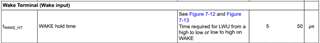
2. What is the edge wake-up voltage threshold for the wake pin of the wake pin?
3. When the TCAN1045 is in sleep mode, is it possible to add a ground capacitor to the wake-up pin to generate a wake-up signal when the Vbattery changes?

  • Hi Baoxiang, 

    Thanks for reaching out! I am reviewing your questions, and I will get a response to you by the end of day tomorrow. 

    Best,

    Ethan

  • Hi Baoxiang,

    Could you please share your exact schematic so I can provide more feedback?

    When the Vbattery voltage is restored to 12V, the TCAN1043 has been in sleep mode due to undervoltage. The INH pin voltage is 0V, which causes the system to fail to power up and system functions cannot be restored.

    This is expected. Since only VCC and VIO were in the undervoltage threshold (not VSUP), TCAN1043-Q1 is still in sleep mode, which keeps INH high impedance. 

    1. The main two ways to enter Standby mode from Sleep mode is either from the CAN bus or the WAKE pin. Additionally, if VSUP falls under the undervoltage threshold of 3V, then device will begin the power-up sequence and enter Standby mode, which raises INH high. 

    2. The Wake pin voltage levels can be found in section 6.7 of the datasheet:

    Here VSUP - 1.9 is the MIN value for a high level input, and VSUP -3.5 is the MAX value for a low level input. Section 8.4.6.2 describes the Wake pin in more detail. 

    3. A capacitor to ground can be added to the Wake pin. Note that in order for the Wake transition to be triggered, the Wake hold time must be longer than 50us:

    You can also directly connect the Wake pin to VSUP. Depending on how fast the VSUP voltage is raised, you might be able to wake up the device from the increase in the VSUP level. 

    Regards,

    Ethan