This thread has been locked.

If you have a related question, please click the "Ask a related question" button in the top right corner. The newly created question will be automatically linked to this question.

THVD9491-SEP: THVD9491-SEP

Part Number: THVD9491-SEP

Tool/software:

Hi,

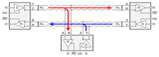
I'm using THD9491-SEP as RS422 transceiver and have some questions:

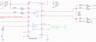
A) For not used transmit side, I assume that DI should be connected to GND while Z, Y should be left floating - please confirm

B) Another question is about the 120R resistors:

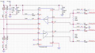
At the EVB document the 120R resistors appears as NC. 

Assuming it will be connected, it is 0805 resistors.

At the DS, the bus voltage can be up to 40V. If so, the 0805 resistor seems too low (power wise).

When does the 120R should be assembled? 

What is the recommended power - Is it 40^2/120 = 13.33W ? This seems unreasonable.

On the other hand, can you explain why EVB 50 ohm is 3.9W?

Thanks,

Zeev.

  • Hi Zeev,

    Thanks for reaching about the THVD9491-SEP.

    A) To use a full-duplex RS-485 device as a receiver only (i.e. RS-422) the unused input D should be tied to GND, which you have done correctly. To conserver power, DE should be low to disabled the driver. 

    B) For the 120 Ohm resistors:

    • 40V is the Absolute Maximum rating the bus pins can handle, which is the built-in protection above the RS-485 standard common mode range (-7V to 12V). The common mode range for this device is an improved symmetric -12 to 12V. So the proper voltage estimate would be 12V not 40V. In this case the estimated power would be around 1.2W as a worse case scenario. 
    • As for the 120 Ohm placement, only the two farthest nodes should have termination such that the bus is properly impedance matched to around 60 Ohms. Any nodes in between should not have termination. It should effectively look something like this:

    If you have any further questions, please let us know!

    -Ethan