This thread has been locked.

If you have a related question, please click the "Ask a related question" button in the top right corner. The newly created question will be automatically linked to this question.

DS90UB962-Q1: I2C data lost between UB962 and UB935

Part Number: DS90UB962-Q1
Other Parts Discussed in Thread: USB2ANY

Tool/software:

Hello TI experts:

we are facing some issues when using the UB962 and UB935.the source tickets can be found here.

e2e.ti.com/.../5623084

We are using the TDA4->UB962->UB935->OVX3F for our video pipline.

and currently we found a issue which happens in a small probability event.

some of the I2C wave lost when we are trying to write some register:

and we connect all I2c between the TDA4 and camera

 for our system we use TDA4->UB963->UB935->x3fcamrea

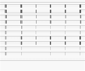
and I measures all I2C in the system which is TDA4 I2c with UB962 and UB935 i2c with x3fcamera as follows

channel 1 2 is for the TDA4 side 

channel 3 4,5 6, 7 8, 9 10 for the x3f camera side

and in the timeline 10.75S here is a no ACK issue here

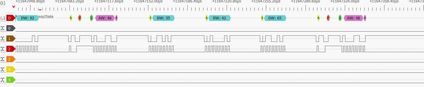
and if I zoom in the waves 

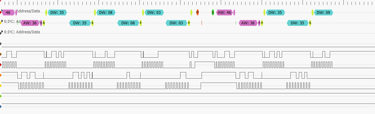
it trying to write some register to camera,

but when address 0x36 and the first reg data 0x35 was write to the camera

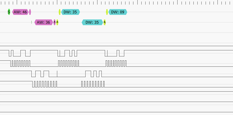
the next data 0x09 have not send by the UB935 

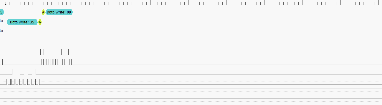
it seems the 0x09 data was lost in the data line.that is very strange here.

could you pls help us why the data lost here.

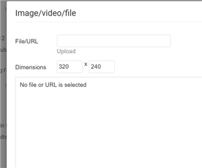
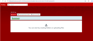
and for the configuration of the UB962 and Ub935 can be found here

e2e.ti.com/.../ds90ub962-q1-ds90ub962-q1-greelysmart-ub962-ub935-register-configuration

  • Hi Yixiao,

    Can you please share the I2C capture so we can take a deeper look? 

    On the UB935, we recommend setting 0xA=0x12, has this been applied to the intialization sequence? 

    Best,

    Zoe

  • Yes,for the 0xA register it is already been 0x12

    the link here is the configuration of UB962 & ub935

    e2e.ti.com/.../ds90ub962-q1-ds90ub962-q1-greelysmart-ub962-ub935-register-configuration
  • Hi Yixiao, 

    Can you provide the I2C log that's pictured in these posts? Not sure if it was provided already. 

    Secondly, can you please provide MAP results for the UB962 and 935 in use here? Is lock stable during this I2C test? 

    Best,

    Zoe

  • Hello Zoe,

    I try to upload the I2C capture but the upload failed it seems the source file was too big to upload,do you have the email or other methods to share the i2c capture file

  • Hi Yixiao, 

    Can you try uploading here?

    https://tidrive.ext.ti.com/u/txG4oq0RuL-lEbix/1ac5c63d-a9b2-415f-b609-babebade341c?l

    Password: YXKw9Q3@

    Best,

    Zoe

  • hello Zoe,

    it was already uploaded and you can open the file by using this tools 

  • Hi Yixiao, 

    Thanks for sharing, let me look into how we can use this file on our end. 

    Taking a step back can you provide some more information on the phenomena being seen here: 

    1. What is the reoccurrence rate? Is this only seen on one system? 
    2. It seems that this occurs when writing to a peripheral on the serializer side. Does this occur when interfacing to only one peripheral? 

    Have MAP and BIST been run on the system to observe link performance? MAP is available to be run on the Analog LaunchPAD software and takes a look at the passing states. For more information on MAP you can refer to the following link: www.ti.com/.../snlu243.pdf

    Best,

    Zoe

  • hello Zoe,

    for the reoccurrence rate all board have the same issue,and for the rate it is about one time each 12 hours,and when this it happens,

    What is the reoccurrence rate? Is this only seen on one system? 

    it happens many times in one power up sequence. just as bellows it happes 5 times in one powerup sequence

    It seems that this occurs when writing to a peripheral on the serializer side. Does this occur when interfacing to only one peripheral? 

    for the questions,we have two peripheral in this channel,which is eeprom and camera,both of them have occurres this issue

    Have MAP and BIST been run on the system to observe link performance

    for the MAP and BIST do we need the EVM board for caputure the data,can we use our ECU to do that?

  • Hi Yixiao, 

    An EVM is not required to run MAP or BIST. In order to use these tests on Analog LaunchPAD software, I2C communication via a USB2ANY or Aardvark is required. Attached is the example scripts for MAP and BIST for I2C communication:


    """
      Copyright 2018 Texas Instruments Incorporated. All rights reserved.
    
      IMPORTANT: Your use of this Software is limited to those specific rights
      granted under the terms of a software license agreement between the user who
      downloaded the software, his/her employer (which must be your employer) and
      Texas Instruments Incorporated (the "License"). You may not use this Software
      unless you agree to abide by the terms of the License. The License limits your
      use, and you acknowledge, that the Software may not be modified, copied or
      distributed unless embedded on a Texas Instruments microcontroller which is
      integrated into your product. Other than for the foregoing purpose, you may
      not use, reproduce, copy, prepare derivative works of, modify, distribute,
      perform, display or sell this Software and/or its documentation for any
      purpose.
    
      YOU FURTHER ACKNOWLEDGE AND AGREE THAT THE SOFTWARE AND DOCUMENTATION ARE
      PROVIDED AS IS WITHOUT WARRANTY OF ANY KIND, EITHER EXPRESS OR IMPLIED,
      INCLUDING WITHOUT LIMITATION, ANY WARRANTY OF MERCHANTABILITY, TITLE,
      NON-INFRINGEMENT AND FITNESS FOR A PARTICULAR PURPOSE. IN NO EVENT SHALL TEXAS
      INSTRUMENTS OR ITS LICENSORS BE LIABLE OR OBLIGATED UNDER CONTRACT,
      NEGLIGENCE, STRICT LIABILITY, CONTRIBUTION, BREACH OF WARRANTY, OR OTHER LEGAL
      EQUITABLE THEORY ANY DIRECT OR INDIRECT DAMAGES OR EXPENSES INCLUDING BUT NOT
      LIMITED TO ANY INCIDENTAL, SPECIAL, INDIRECT, PUNITIVE OR CONSEQUENTIAL
      DAMAGES, LOST PROFITS OR LOST DATA, COST OF PROCUREMENT OF SUBSTITUTE GOODS,
      TECHNOLOGY, SERVICES, OR ANY CLAIMS BY THIRD PARTIES (INCLUDING BUT NOT
      LIMITED TO ANY DEFENSE THEREOF), OR OTHER SIMILAR COSTS.
    
      Should you have any questions regarding your right to use this Software,
      contact Texas Instruments Incorporated at www.TI.com.
    
    """
    # Name: ub962_margin_analysis.py
    # Purpose: Margin Analysis Script for DS90UB962
    # Version 0.5
    # Run from DES
    
    print "\n"
    
    import time
    import logging
    
    # Select log file name and log level(DEBUG, INFO)
    logging.basicConfig(filename='ub962sfeq_testlog.log', filemode='a', format='%(levelname)s:%(message)s',level=logging.DEBUG)
    
    # Select RX Port: RX_PORT0_962B or RX_PORT1_962B or RX_PORT2_962B or RX_PORT3_962B
    CONST_RXPORT = 'RX_PORT0_962B'
    
    # configure I2C device ID of the DES per IDX strap pin
    # EVM: 0x7A, SVB: 0x7A, Custom Board: 0x??
    devAddr_DES = 0x7A
    
    f1=open('./ub962sfeq_test.csv', 'w+')
    f1.write(",,,,,,,,SP,,,,,,,,")
    f1.write("\r")
    f1.write("EQ,0,1,2,3,4,5,6,7,8,9,10,11,12,13,14")


    # default (0x83) is for port0, for port1 would need to change thie to be 0x97.
    if CONST_RXPORT == 'RX_PORT0_962B':
    	#set RX_PORT_CTL register
    	board.WriteI2C(devAddr_DES,0x0C,0x0F)
    	time.sleep(0.1)
    	#set FPD3_PORT_SEL register
    	board.WriteI2C(devAddr_DES,0x4c,0x01)
    	time.sleep(0.1)
    	# choose analog register page
    	board.WriteI2C(devAddr_DES, 0xB0, 0x04)
    	time.sleep(0.1)
    elif CONST_RXPORT == 'RX_PORT1_962B':
    	#set RX_PORT_CTL register
    	board.WriteI2C(devAddr_DES, 0x0C, 0x0F)
    	time.sleep(0.1)
    	#set FPD3_PORT_SEL register
    	board.WriteI2C(devAddr_DES,0x4c,0x12)
    	time.sleep(0.1)
    	# choose analog register page
    	board.WriteI2C(devAddr_DES, 0xB0, 0x08)
    	time.sleep(0.1)
    elif CONST_RXPORT == 'RX_PORT2_962B':
    	#set RX_PORT_CTL register
    	board.WriteI2C(devAddr_DES, 0x0C, 0x0F)
    	time.sleep(0.1)
    	#set FPD3_PORT_SEL register
    	board.WriteI2C(devAddr_DES,0x4c,0x24)
    	time.sleep(0.1)
    	# choose analog register page
    	board.WriteI2C(devAddr_DES, 0xB0, 0x0C)
    	time.sleep(0.1)	
    elif CONST_RXPORT == 'RX_PORT3_962B':
    	#set RX_PORT_CTL register
    	board.WriteI2C(devAddr_DES, 0x0C, 0x0F)
    	time.sleep(0.1)
    	#set FPD3_PORT_SEL register
    	board.WriteI2C(devAddr_DES,0x4c,0x38)
    	time.sleep(0.1)
    	# choose analog register page
    	board.WriteI2C(devAddr_DES, 0xB0, 0x10)
    	time.sleep(0.1)	
    else:
    	#set RX_PORT_CTL register
    	board.WriteI2C(devAddr_DES,0x0C,0x0F)
    	time.sleep(0.1)
    	#set FPD3_PORT_SEL register
    	board.WriteI2C(devAddr_DES,0x4c,0x01)
    	time.sleep(0.1)
    	# choose analog register page
    	board.WriteI2C(devAddr_DES, 0xB0, 0x04)
    	time.sleep(0.1)
    
    # choose reg_8 @ offset 8
    board.WriteI2C(devAddr_DES, 0xB1, 0x08)
    time.sleep(0.1)
    # configure AEQ_CTL register: Disable SFILTER adaption with AEQ
    board.WriteI2C(devAddr_DES, 0x42, 0x70)
    time.sleep(0.1)
    # set AEQ Bypass register: bypass AEQ, STAGE1=0, STAGE2=0, Lock Mode = 1
    board.WriteI2C(devAddr_DES, 0xD4, 0x01)
    time.sleep(0.1)
    # set Parity Error Threshold Hi Register 
    board.WriteI2C(devAddr_DES, 0x05, 0x00)
    time.sleep(0.1)
    # set Parity Error Threshold Lo Register 
    board.WriteI2C(devAddr_DES, 0x06, 0x01)
    time.sleep(0.1)
    # enable LINK_ERR_COUNT and LINK_SFIL_WAIT
    board.WriteI2C(devAddr_DES, 0xB9, 0x33)
    # Enable Encoder CRC error capability
    enc_crc = board.ReadI2C(devAddr_DES, 0x4A, 0x01)
    board.WriteI2C(devAddr_DES, 0x4A, (enc_crc | 0x10))
    # Enable Encoder CRC
    enc_crc = board.ReadI2C(devAddr_DES, 0xBA, 0x01)
    board.WriteI2C(devAddr_DES, 0xBA, (enc_crc & 0x7F))
    
    logging.info('**** Begin Initial Settings ****')
    logging.info('Test lock status with sfilter changes')
    logging.info('Check RX_PORT_CTL Register (0x0C): %s', hex(board.ReadI2C(devAddr_DES, 0x0C, 1)))
    logging.info('Select PORT 0 (0x4C): %s', hex(board.ReadI2C(devAddr_DES, 0x4c)))
    logging.info('Check RX_PORT_STS1 Register (0x4D): %s', hex(board.ReadI2C(devAddr_DES, 0x4D, 1)))
    logging.info('Check Device Status Register (0x04): %s', hex(board.ReadI2C(devAddr_DES, 0x04,1)))
    logging.info('Disable sfilter adaption in AEQ_CTL register (0x42): %s', hex(board. ReadI2C(devAddr_DES, 0x42)))
    logging.info('Check AEQ_CTL2 register (0xD2): %s', hex(board.ReadI2C(devAddr_DES, 0xD2,1)))
    logging.info('Check AEQ MIN/MAX register (0xD5): %s', hex(board.ReadI2C(devAddr_DES, 0xD5,1)))
    logging.info('Check AEQ BYPASS register (0xD4): %s', hex(board.ReadI2C(devAddr_DES, 0xD4,1)))
    logging.info('reg_8 initial value: %s', hex(board.ReadI2C(devAddr_DES, 0xB2)))
    logging.info('Updated AEQ BYPASS register (0xD4): %s', hex(board.ReadI2C(devAddr_DES, 0xD4,1)))
    logging.info('**** End Initial Settings ****')
    
    # delay before lock is checked, use minimum of 0.5 when doing digital reset
    dwell_time = 0.9
    
    for y in range(0,1):
    	eq_sel2 = 0
    	#eq_sel1 is needed from 0 to 7
    	for eq_sel1 in range(0, 8, 1):
    		board.WriteI2C(devAddr_DES, 0xD4, ((eq_sel1<<5)+(eq_sel2<<1)+0x01))
    		time.sleep(0.1)
    		logging.debug('AEQ BYPASS register (0xD4): %s', hex(board.ReadI2C(devAddr_DES, 0xD4,1)))
    		time.sleep(0.1)
    		logging.info('%s', hex(eq_sel1))
    		print 'eq_sel1= ', hex(eq_sel1)
    		print 'lock status:'
    		f1.write("\r")
    		out_string = str(eq_sel1) + ","
    		f1.write(out_string)
    		ddly_ctrl = 8
    		# choose reg_9 @ offset 9
    		board.WriteI2C(devAddr_DES, 0xB1, 0x09)
    		time.sleep(0.1)	
    		# write reg_9
    		board.WriteI2C(devAddr_DES, 0xB2, ddly_ctrl)
    		time.sleep(0.1)		 
    		for cdly_ctrl in range(15, 8, -1):
    			#select reg_8 @ offset 8
    			board.WriteI2C(devAddr_DES, 0xB1, 0x08)
    			time.sleep(0.1)			
    			# write reg_8
    			board.WriteI2C(devAddr_DES, 0xB2, cdly_ctrl)
    			time.sleep(0.1)
    			logging.debug('**reg_8 updated value**: %s', hex(board.ReadI2C(devAddr_DES, 0xB2)))
    			# reset digital block except registers
    			board.WriteI2C(devAddr_DES, 0x01, 0x01)
    			time.sleep(dwell_time)
    			port_status1 = board.ReadI2C(devAddr_DES, 0x4D,1)
    			logging.debug('Check RX_PORT_STS1 Register (0x4D): %s', hex(port_status1))
    			time.sleep(0.1)
    			logging.debug('port lock status: %s', hex(port_status1 & 0x01))
    			time.sleep(0.1)
    			port_status2 = board.ReadI2C(devAddr_DES, 0x4E,1)
    			logging.debug('Check RX_PORT_STS2 Register (0x4E): %s', hex(port_status2))
    			time.sleep(0.1)			
    			lock_status = 0
    			lock_sum = 0
    			for loop in range(0, 10, 1):
    				port_status1 = board.ReadI2C(devAddr_DES, 0x4D, 1)
    				time.sleep(0.1)
    				port_status2 = board.ReadI2C(devAddr_DES, 0x4E, 1)
    				time.sleep(0.1)				
    				if (((port_status1 & 0x3C) == 0) and ((port_status2 & 0x20) == 0)):
    					lock_sum += int(port_status1 & 0x01)
    				else:
    					board.ReadI2C(devAddr_DES, 0x56, 1) # clear parity error
    					board.ReadI2C(devAddr_DES, 0x47, 1) # 
    				time.sleep(0.1)
    			lock_avg = round(float(lock_sum) / 10, 2)
    			lock_str = "%0.1f" %lock_avg
    			logging.debug('port lock status: %s', lock_str)
    			time.sleep(0.1)
    			out_string = lock_str + ","
    			f1.write(out_string)
    			print lock_str
    		logging.debug('**cdly_ctrl value at end of loop**: %s', hex(cdly_ctrl))
    		cdly_ctrl = 8
    		# choose reg_8 @ offset 8
    		board.WriteI2C(devAddr_DES, 0xB1, 0x08)
    		time.sleep(0.1)	
    		# write reg_8
    		board.WriteI2C(devAddr_DES, 0xB2, cdly_ctrl)
    		time.sleep(0.1)		 
    		for ddly_ctrl in range(8, 16, 1):
    			#select reg_9 @ offset 9
    			board.WriteI2C(devAddr_DES, 0xB1, 0x09)
    			time.sleep(0.1)			
    			# write reg_9
    			board.WriteI2C(devAddr_DES, 0xB2, ddly_ctrl)
    			time.sleep(0.1)
    			logging.debug('**reg_9 updated value**: %s', hex(board.ReadI2C(devAddr_DES, 0xB2)))
    			# reset digital block except registers
    			board.WriteI2C(devAddr_DES, 0x01, 0x01)
    			time.sleep(dwell_time)
    			port_status1 = board.ReadI2C(devAddr_DES, 0x4D,1)
    			logging.debug('Check RX_PORT_STS1 Register (0x4D): %s', hex(port_status1))
    			time.sleep(0.1)
    			logging.debug('port lock status: %s', hex(port_status1 & 0x01))
    			time.sleep(0.1)
    			port_status2 = board.ReadI2C(devAddr_DES, 0x4E,1)
    			logging.debug('Check RX_PORT_STS2 Register (0x4E): %s', hex(port_status2))
    			time.sleep(0.1)			
    			lock_status = 0
    			lock_sum = 0
    			for loop in range(0, 10, 1):
    				port_status1 = board.ReadI2C(devAddr_DES, 0x4D, 1)
    				time.sleep(0.1)
    				port_status2 = board.ReadI2C(devAddr_DES, 0x4E, 1)
    				time.sleep(0.1)				
    				if (((port_status1 & 0x3C) == 0) and ((port_status2 & 0x20) == 0)):	
    					lock_sum += int(port_status1 & 0x01)
    				else:
    					board.ReadI2C(devAddr_DES, 0x56, 1) # clear parity error
    					board.ReadI2C(devAddr_DES, 0x47, 1) # 
    				time.sleep(0.1)
    			lock_avg = round(float(lock_sum) / 10, 2)
    			lock_str = "%0.1f" %lock_avg
    			logging.debug('port lock status: %s', lock_str)
    			time.sleep(0.1)
    			out_string = lock_str + ","
    			f1.write(out_string)
    			print lock_str
    	
    	eq_sel1 = 7
    	#eq_sel2 is needed only from 1 to 7
    	for eq_sel2 in range(1, 8, 1):						
    		board.WriteI2C(devAddr_DES, 0xD4, ((eq_sel1<<5)+(eq_sel2<<1)+0x01))
    		time.sleep(0.1)
    		logging.debug('AEQ BYPASS register (0xD4): %s', hex(board.ReadI2C(devAddr_DES, 0xD4,1)))
    		time.sleep(0.1)
    		logging.info('%s', hex(eq_sel2))
    		print 'eq_sel2= ', hex(eq_sel2)
    		print 'lock status:'
    		f1.write("\r")
    		out_string = str(eq_sel1+eq_sel2) + ","
    		f1.write(out_string)	
    		ddly_ctrl = 8
    		# choose reg_9 @ offset 9
    		board.WriteI2C(devAddr_DES, 0xB1, 0x09)
    		time.sleep(0.1)	
    		# write reg_9
    		board.WriteI2C(devAddr_DES, 0xB2, ddly_ctrl)
    		time.sleep(0.1)		
    		for cdly_ctrl in range(15, 8, -1):
    			#select reg_8 @ offset 8
    			board.WriteI2C(devAddr_DES, 0xB1, 0x08)
    			time.sleep(0.1)		
    			# write reg_8
    			board.WriteI2C(devAddr_DES, 0xB2, cdly_ctrl)
    			time.sleep(0.1)
    			logging.debug('**reg_8 updated value**: %s', hex(board.ReadI2C(devAddr_DES, 0xB2)))
    			# reset digital block except registers
    			board.WriteI2C(devAddr_DES, 0x01, 0x01)
    			time.sleep(dwell_time)
    			port_status1 = board.ReadI2C(devAddr_DES, 0x4D,1)
    			logging.debug('Check RX_PORT_STS1 Register (0x4D): %s', hex(port_status1))
    			time.sleep(0.1)
    			logging.debug('port lock status: %s', hex(port_status1 & 0x01))
    			time.sleep(0.1)
    			port_status2 = board.ReadI2C(devAddr_DES, 0x4E,1)
    			logging.debug('Check RX_PORT_STS2 Register (0x4E): %s', hex(port_status2))
    			time.sleep(0.1)			
    			lock_status = 0
    			lock_sum = 0
    			for loop in range(0, 10, 1):
    				port_status1 = board.ReadI2C(devAddr_DES, 0x4D, 1)
    				time.sleep(0.1)
    				port_status2 = board.ReadI2C(devAddr_DES, 0x4E, 1)
    				time.sleep(0.1)				
    				if (((port_status1 & 0x3C) == 0) and ((port_status2 & 0x20) == 0)):
    					lock_sum += int(port_status1 & 0x01)
    				else:
    					board.ReadI2C(devAddr_DES, 0x56, 1) # clear parity error
    					board.ReadI2C(devAddr_DES, 0x47, 1) # 
    				time.sleep(0.1)
    			lock_avg = round(float(lock_sum) / 10, 2)
    			lock_str = "%0.1f" %lock_avg
    			logging.debug('port lock status: %s', lock_str)
    			time.sleep(0.1)
    			out_string = lock_str + ","
    			f1.write(out_string)
    			print lock_str
    		logging.debug('**cdly_ctrl value at end of loop**: %s', hex(cdly_ctrl))
    		cdly_ctrl = 8
    		#select reg_8 @ offset 8
    		board.WriteI2C(devAddr_DES, 0xB1, 0x08)
    		time.sleep(0.1)		
    		# write reg_8
    		board.WriteI2C(devAddr_DES, 0xB2, cdly_ctrl)
    		time.sleep(0.1)		
    		for ddly_ctrl in range(8, 16, 1):
    			#select reg_9 @ offset 9
    			board.WriteI2C(devAddr_DES, 0xB1, 0x09)
    			time.sleep(0.1)			
    			# write reg_9
    			board.WriteI2C(devAddr_DES, 0xB2, ddly_ctrl)
    			time.sleep(0.1)
    			logging.debug('**reg_9 updated value**: %s', hex(board.ReadI2C(devAddr_DES, 0xB2)))
    			# reset digital block except registers
    			board.WriteI2C(devAddr_DES, 0x01, 0x01)
    			time.sleep(dwell_time)
    			port_status1 = board.ReadI2C(devAddr_DES, 0x4D,1)
    			logging.debug('Check RX_PORT_STS1 Register (0x4D): %s', hex(port_status1))
    			time.sleep(0.1)
    			logging.debug('port lock status: %s', hex(port_status1 & 0x01))
    			time.sleep(0.1)
    			port_status2 = board.ReadI2C(devAddr_DES, 0x4E,1)
    			logging.debug('Check RX_PORT_STS2 Register (0x4E): %s', hex(port_status2))
    			time.sleep(0.1)			
    			lock_status = 0
    			lock_sum = 0
    			for loop in range(0, 10, 1):
    				port_status1 = board.ReadI2C(devAddr_DES, 0x4D, 1)
    				time.sleep(0.1)
    				port_status2 = board.ReadI2C(devAddr_DES, 0x4E, 1)
    				time.sleep(0.1)				
    				if (((port_status1 & 0x3C) == 0) and ((port_status2 & 0x20) == 0)):
    					lock_sum += int(port_status1 & 0x01)
    				else:
    					board.ReadI2C(devAddr_DES, 0x56, 1) # clear parity error
    					board.ReadI2C(devAddr_DES, 0x47, 1) # 	
    				time.sleep(0.1)
    			lock_avg = round(float(lock_sum) / 10, 2)
    			lock_str = "%0.1f" %lock_avg
    			logging.debug('port lock status: %s', lock_str)
    			time.sleep(0.1)
    			out_string = lock_str + ","
    			f1.write(out_string)
    			print lock_str
    
    #select reg_9 @ offset 9
    board.WriteI2C(devAddr_DES, 0xB1, 0x09)
    time.sleep(0.1)		
    # write reg_9 default value
    board.WriteI2C(devAddr_DES, 0xB2, 0x0)
    time.sleep(0.1)
    
    #select reg_8 @ offset 8
    board.WriteI2C(devAddr_DES, 0xB1, 0x08)
    time.sleep(0.1)
    # write reg_8 default value
    board.WriteI2C(devAddr_DES, 0xB2, 0x0)
    time.sleep(0.1)
    
    #do a final digital reset including registers
    board.WriteI2C(devAddr_DES, 0x01, 0x02)
    time.sleep(0.1)
    
    #readback RX_PORT_STS1 to clear Lock status changed on RX Port 0
    board.ReadI2C(devAddr_DES, 0x4D, 1)
    time.sleep(0.1)
    
    logging.debug('reg_8 default value: %s', hex(board.ReadI2C(devAddr_DES, 0xB2)))
    time.sleep(0.1)
    
    logging.debug('DES lock & pass: %s', hex(board.ReadI2C(devAddr_DES, 0x04,1)))
    time.sleep(0.1)
    
    f1.close()
    

    The below script was devoloped for 954 and 953 BIST however this will follow the same set up as 954 BIST. Please ensure the correct IDX addresses and ports are selected with the script. 

    ## BIST_953_954_WithForcedError.py
    ##
    ## revision 1.1 June 13, 2017
    ##
    ########
    ######################
    ##
    ## This script file is used to check the link between the 953 and 954
    ##
    ## The Built In Self Test (BIST) generates a puesdo random sequence
    ## and checks for CRC errors between transmitted and received sequence.
    ##
    ## Rev. 1.1
    ## Added Parity Errors, restructured code
    ##
    ##
    ######################
    
    print "\n\n"
    import time
    
    
    #	Define 954 and 953 Adresses
    UB953 = 0x18																#953 SER Alias ID, check 0x5C on 954 for confirmation 
    UB954 = 0x7a																#954 Device ID, check 0x00 on 954 for confirmation
    
    #	Port selection, Passthrough, and aliasing
    #board.WriteI2C(UB954, 0x4C, 0x01)											#Enable Port 0 writes
    #board.WriteI2C(UB954, 0x58, 0x5E)											#I2C Pass through Enabled and BC = 50Mbps
    #board.WriteI2C(UB954, 0x5C, 0x18)											#953 Alias defined as 0x18
    
    
    #	Digital Reset except for registers
    board.WriteI2C(UB953, 0x01, 0x01)											#Resets 953
    time.sleep(0.5)
    board.WriteI2C(UB954, 0x01, 0x01)											#Resets 954
    time.sleep(0.5)
    
    print ("Devices Reset")


    #	Confirm Devices can communicate with each other
    print ("954 Device ID (0x00):", hex(board.ReadI2C(UB954, 0x00, 1)))			#954 Device ID, should be 0x7A, check 0x00 for confirmation
    time.sleep(0.5)
    print ("953 Device ID (0x00):", hex(board.ReadI2C(UB953, 0x00, 1)))			#953 Device ID, should be 0x30, check 0x5B for confirmation
    
    print ("------------------------------------------------------------------")
    time.sleep(0.5)


    #	Read Reciever Lock Status
    print ("Reciever Lock Status (0x04):", hex(board.ReadI2C(UB954, 0x04, 0x1)))						#0x04 is DEVICE_STS of 954
    print ("Should read 0xDF")
    
    print ("------------------------------------------------------------------")
    time.sleep(1)


    #	Enable write for Port0 of FPD3_PORT_SEL 
    board.WriteI2C(UB954, 0x4C, 0x01)											#0x4C is FPD3_PORT_SEL


    #	Clear Errors and Error Count
    board.WriteI2C(UB953, 0x49, 0x28)											#0x49 is BC_CTRL. 0x28 selects BIST_CRC ERR CLR and CRC ERR CLR
    
    print ("Read BCC Error Status (0x79):", hex(board.ReadI2C(UB953, 0x79, 1)))	#Clear possible BCC_Error by Reading BCC Error Status
    print ("Consult Register 0x79 on the SER for more information")
    
    print ("------------------------------------------------------------------")
    
    print ("Pre-Error Link Status of 953 (0x52):", hex(board.ReadI2C(UB953, 0x52,1)))					#0x52 is GENERAL_STS of 953
    print ("Should read 0x45 = RX Lock Detect, HS PLL Lock, Link Detect")
    
    print ("------------------------------------------------------------------")
    
    print ("BIST CRC Error count (0x54) on 953 before forced error.", hex(board.ReadI2C(UB953, 0x54, 1)))#0x54 is BIST ERR CNT
    
    print ("------------------------------------------------------------------")
    
    time.sleep(1)


    #	Enabling BIST, Error, and Lock-Change Status
    print ("Read BIST CTL register (0xB3) Before BIST ENABlED", hex(board.ReadI2C(UB954, 0xB3, 1)))		#0xB3 is BIST_CTL, bit 1 controls if enabled or not
    print ("Should read 0x00 or 0x08\n")
    
    board.WriteI2C(UB954, 0xB3, 0x01)											#Enable BIST using BIST_CTL
    
    print ("Read BIST CTL (0xB3) register After BIST ENABLED", hex(board.ReadI2C(UB954, 0xB3, 1)))		#0xB3 is BIST_CTL
    print ("Should read 0x01")
    
    time.sleep(0.25)
    print ("------------------------------------------------------------------")
    print ("Read BIST Lock Status Change of 954 RIGHT AFTER BIST enabled (0x4D):", hex(board.ReadI2C(UB954, 0x4D,1)))		#0x4D is RX_PORT_STS1 of 954
    print ("Read to clear BIST enable Lock Status Change.")
    
    
    board.WriteI2C(UB954, 0xD0, 0x01)											#Force 1 Error, 0xD0 is PORT_DEBUG register
    
    #board.WriteI2C(UB954, 0xD0, 0x02)											#Force Continious errors, 0xD0 is PORT_DEBUG register
    time.sleep(10)																#Can run BIST for as long as needed
    #board.WriteI2C(UB954, 0xD0, 0x00)											#If forced continious errors, stop forcing errors
    
    print ("Read Post-BIST Lock Status Change of 954 RIGHT BEFORE BIST disabled (0x4D):", hex(board.ReadI2C(UB954, 0x4D,1)))		#0x4D is RX_PORT_STS1 of 954
    print ("Should read 0x03, If lock status changed during BIST, will read 0x13")


    #	Disable BIST and Port0
    board.WriteI2C(UB954, 0xB3, 0x00)											#Disable BIST, using BIST_CTL
    board.WriteI2C(UB954, 0x4C, 0x00)											#0x4C is FPD3_PORT_SEL
    
    print ("------------------------------------------------------------------")
    time.sleep(1)


    #	Check if Error(s) occured
    print ("Post-Error Link Status of 953 (0x52):", hex(board.ReadI2C(UB953, 0x52,1)))					#0x52 is GENERAL_STS of 953
    print "Should read 0x4D = RX Lock Detect, HS PLL Lock, Link Detect, and BIST CRC Error"
    
    print ("Reciever Lock Status (0x04):", hex(board.ReadI2C(UB954, 0x04, 0x1))) 						#0x04 is DEVICE_STS of 954
    print ("Should read 0xDF")
    
    
    print ("------------------------------------------------------------------")
    
    print ("BIST CRC Error count (0x54) on 953.", hex(board.ReadI2C(UB953, 0x54, 1))) #0x54 is BIST ERR CNT
    print ("Parity Error count MSB (0x56) on 954.", hex(board.ReadI2C(UB954, 0x56, 1))) #0x56 is number of Parity error 8 most significant bits
    print ("Parity Error count LSB (0x55) on 954.", hex(board.ReadI2C(UB954, 0x55, 1))) #0x55 is number of Parity error 8 least significant bits
    
    
    print ("------------------------------------------------------------------")
    
    #print ("953 Device ID (0x00):", hex(board.ReadI2C(UB953, 0x00, 1)))			#953 Device ID, should be 0x30, check 0x5B for confirmation, 
    																				#Usually use this to see if 954 is stuck in BIST mode
    
    #	Clear BIST Errors on 953
    board.WriteI2C(UB953, 0x49, 0x28)											#0x49 is BC_CTRL. 0x28 selects BIST_CRC ERR CLR and CRC ERR CLR
    
    print "\n\n" 																#New line Printed
    

    Best,

    Zoe

  • Hello Zoe,

    here is the MAP result,it seems the port3 have the issue,and what the data lost was in port 3

  • Hi Yixiao, 

    By default the device will start AEQ at an EQ level of 2. Would you be able to test lowering the AEQ floor for port 3 so that EQ levels 0 and 1 are included in this search and see if this improves results? 

    This can be done via the following in the initialization script:

    1. Select RX port 3 0x4C=0x38
    2. Disable SET_AEQ_FLOOR 0x92=0x90
    3. Restart AEQ 0x92=0x98

    Best,

    Zoe

  • Hello Zoe,

    But the port 3 already does not recommend,should we check the hardware design for that?

  • Hi Yixiao, 

    This is correct, port 3 is not meeting the recommended passing criteria for the Margin Analysis Program. We would need to take a look at the hardware design in order to improve the margin here. 

    The scripting changes were recommended from a debugging perspective as it provides more passing states in AEQ to see if a lower EQ setting may help performance here. 

    Some examples for what may be impacting the margin analysis results are listed below: 

    1. Power over Coax noise
    2. Insertion loss and return loss characteristics 
      1. Cable type and length
      2. PCB board layout
    3. Hardware connections

    Would you be able to provide the schematic and layout for review with this in mind? 

    Best,

    Zoe

  • Hello Zoe,

    our hardware team actully already notice that,and they designed another layout for the new ECU,yesterday I get the new ECU and I use new ECU to get map

    here is the result 

  • Hi Yixiao, 

    Great! Is this same phenomena occurring using the new ECU? 

  • Hello Zoe,

    after the stress test,it seems that the phenomena disappeared,but we need the root reason why the I2C data lost,because even though the map is not recommanded in port3 but the camera video frame through the FPDlink is normal,why it can influence the I2C data.

  • Hi Yixiao, 

    MAP will take a look specifically at the forward channel from the serializer and provide a sense of forward channel link margin. A block will be considered red if the following error conditions are observed: 

    • BCC_CRC_ERROR: Forward channel CRC error detected
    • LOCK_STS_CHG: Lock status has changed since the last time this register was read
    • BCC_SEQ_ERROR: Forward channel sequence error detected
    • PARITY_ERROR: Number of parity errors detected has exceed the programmed threshold (set to one error by the Margin Analysis Tool)
    • FPD3_ENCODING_ERROR: Forward channel encoding error

    These errors will not always directly impact the video data being transmitted and pertain to the forward channel protocol. Errors in the video data would be observed via CSI-2 errors or similar. 

    Since the phenomena does not reoccur with the new ECU, I will mark this thread as closed. Please feel free to reopen by providing another response if this is seen to occur. 

    Best,

    Zoe