This thread has been locked.

If you have a related question, please click the "Ask a related question" button in the top right corner. The newly created question will be automatically linked to this question.

TLK10232: Design and debug questions

Part Number: TLK10232

Tool/software:

We have a few more questions regarding the use of TLK10232. These are:

* REFCLK connection
- What are the termination requirements for the REFCLK inputs when using an 156.25MHz LVPECL oscillator as clock source? Is there a reference circuit available. The EVM schematics show a direct connection from the AC coupling capacitors ti the TLK pins.
- How critical is the rise/fall time requirement? It looks not easy to find LVPECL/LVDS oscillators which safely guarantee meeting the maximum value. Are there any oscillator recommendations?

* Additional documentation
The data sheet states in table 8-22 "Refer to TLK10232 Bringup Procedure (a separate document) for more information.". How can we access this separate document?

* XAUI link/bridge not free of errors
On the LS/XAUI side we have the TLK device connected to a NWP (MCHP) on one channel and a 10GPHY (MCHP) on the other channel. In one scenario we have bridged the 2 channels using the internal switch (see my other E2E post). While in general this bridge is working we face the fact that a very small amount of FCS errors being reported by both XAUI link partners (NWP, PHY).
It must be noted that during this test nothing was connected to the HS/KR side.

A register dump of the 0x1E device (VENDOR SPECIFIC) in the XAUI bridge configuration looks like this (PHY side):
reg value description
1Ex0000 0x0610 GLOBAL_CONTROL_1
1Ex0001 0x0b24 CHANNEL_CONTROL_1
1Ex0002 0x831d HS_SERDES_CONTROL_1
1Ex0003 0xa848 HS_SERDES_CONTROL_2
1Ex0004 0x1500 HS_SERDES_CONTROL_3
1Ex0005 0x2000 HS_SERDES_CONTROL_4
1Ex0006 0xf115 LS_SERDES_CONTROL_1
1Ex0007 0x0000 LS_SERDES_CONTROL_2
1Ex0008 0x0000 LS_SERDES_CONTROL_3
1Ex0009 0x0380 HS_OVERLAY_CONTROL
1Ex000A 0x1fff LS_OVERLAY_CONTROL
1Ex000B 0x0d10 LOOPBACK_TP_CONTROL
1Ex000C 0x0371 LS_CONFIG_CONTROL
1Ex000D 0x2f80 CLK_CONTROL
1Ex000E 0x0000 RESET_CONTROL
1Ex000F 0x70af CHANNEL_STATUS_1
1Ex0010 0x0000 HS_ERROR_COUNTER
1Ex0011 0x0000 LS_LN0_ERROR_COUNTER
1Ex0012 0x0000 LS_LN1_ERROR_COUNTER
1Ex0013 0x0000 LS_LN2_ERROR_COUNTER
1Ex0014 0x0000 LS_LN3_ERROR_COUNTER
1Ex0015 0x4146 LS_STATUS_1 (lane0)
1Ex0015 0x4146 LS_STATUS_1 (lane1)
1Ex0015 0x4146 LS_STATUS_1 (lane2)
1Ex0015 0x4146 LS_STATUS_1 (lane3)
1Ex0016 0xf006 HS_STATUS_1
1Ex0017 0x2000 DST_CONTROL_1
1Ex0018 0x0c20 DST_CONTROL_2
1Ex0019 0x2500 DSR_CONTROL_1
1Ex001A 0xac20 DSR_CONTROL_2
1Ex001B 0x1043 DATA_SWITCH_STATUS
1Ex001C 0x0000 LS_CH_CONTROL_1
1Ex001D 0x0000 HS_CH_CONTROL_1
1Ex001E 0x0000 EXT_ADDRESS_CONTROL
1Ex001F 0x0000 EXT_ADDRESS_DATA
1Ex8003 0x0283 VS_10G_LN_ALIGN_ACODE_P
1Ex8004 0x017c VS_10G_LN_ALIGN_ACODE_N
1Ex8021 0x000f MC_AUTO_CONTROL
1Ex802A 0x02fd DST_ON_CHAR_CONTROL
1Ex802B 0x02fd DST_OFF_CHAR_CONTROL
1Ex802C 0x0207 DST_STUFF_CHAR_CONTROL
1Ex802D 0x02fd DSR_ON_CHAR_CONTROL
1Ex802E 0x02fd DSR_OFF_CHAR_CONTROL
1Ex802F 0x0207 DSR_STUFF_CHAR_CONTROL
1Ex8040 0x0000 LATENCY_MEASURE_CONTROL
1Ex8041 0x0000 LATENCY_COUNTER_2
1Ex8042 0x0000 LATENCY_COUNTER_1
1Ex8100 0x0000 TRIGGER_LOAD_CONTROL
1Ex8101 0x0000 TRIGGER_EN_CONTROL


A register dump of the 0x1E device (VENDOR SPECIFIC) in the XAUI bridge configuration looks like this (NWP side):
reg value description
1Ex0000 0x0610 GLOBAL_CONTROL_1
1Ex0001 0x0b24 CHANNEL_CONTROL_1
1Ex0002 0x831d HS_SERDES_CONTROL_1
1Ex0003 0xa848 HS_SERDES_CONTROL_2
1Ex0004 0x1500 HS_SERDES_CONTROL_3
1Ex0005 0x2000 HS_SERDES_CONTROL_4
1Ex0006 0xf115 LS_SERDES_CONTROL_1
1Ex0007 0x0000 LS_SERDES_CONTROL_2
1Ex0008 0x0000 LS_SERDES_CONTROL_3
1Ex0009 0x0380 HS_OVERLAY_CONTROL
1Ex000A 0x1fff LS_OVERLAY_CONTROL
1Ex000B 0x0d10 LOOPBACK_TP_CONTROL
1Ex000C 0x0371 LS_CONFIG_CONTROL
1Ex000D 0x2f80 CLK_CONTROL
1Ex000E 0x0000 RESET_CONTROL
1Ex000F 0x70af CHANNEL_STATUS_1
1Ex0010 0x0000 HS_ERROR_COUNTER
1Ex0011 0x0000 LS_LN0_ERROR_COUNTER
1Ex0012 0x0000 LS_LN1_ERROR_COUNTER
1Ex0013 0x0000 LS_LN2_ERROR_COUNTER
1Ex0014 0x0000 LS_LN3_ERROR_COUNTER
1Ex0015 0x4142 LS_STATUS_1 (lane0)
1Ex0015 0x4142 LS_STATUS_1 (lane1)
1Ex0015 0x4142 LS_STATUS_1 (lane2)
1Ex0015 0x4142 LS_STATUS_1 (lane3)
1Ex0016 0xf006 HS_STATUS_1
1Ex0017 0x2000 DST_CONTROL_1
1Ex0018 0x0c20 DST_CONTROL_2
1Ex0019 0x2500 DSR_CONTROL_1
1Ex001A 0xac20 DSR_CONTROL_2
1Ex001B 0x1043 DATA_SWITCH_STATUS
1Ex001C 0x0000 LS_CH_CONTROL_1
1Ex001D 0x0000 HS_CH_CONTROL_1
1Ex001E 0x0000 EXT_ADDRESS_CONTROL
1Ex001F 0x0000 EXT_ADDRESS_DATA
1Ex8003 0x0283 VS_10G_LN_ALIGN_ACODE_P
1Ex8004 0x017c VS_10G_LN_ALIGN_ACODE_N
1Ex8021 0x000f MC_AUTO_CONTROL
1Ex802A 0x02fd DST_ON_CHAR_CONTROL
1Ex802B 0x02fd DST_OFF_CHAR_CONTROL
1Ex802C 0x0207 DST_STUFF_CHAR_CONTROL
1Ex802D 0x02fd DSR_ON_CHAR_CONTROL
1Ex802E 0x02fd DSR_OFF_CHAR_CONTROL
1Ex802F 0x0207 DSR_STUFF_CHAR_CONTROL
1Ex8040 0x0000 LATENCY_MEASURE_CONTROL
1Ex8041 0x0000 LATENCY_COUNTER_2
1Ex8042 0x0000 LATENCY_COUNTER_1
1Ex8100 0x0000 TRIGGER_LOAD_CONTROL
1Ex8101 0x0000 TRIGGER_EN_CONTROL

Any recommendations to debug this issue would be highly appreciated.
Thank you very much in advance for feedback & support!

BR
Joerg

  • Hi Joerg,

    I'm still looking into this and will get back to you with feedback by early next week.

    Best,

    Lucas

  • Hi Joerg,

    My apologies for the delay.

    Regarding REFCLK:

    • REFCLK input should have 100-ohm differential impedance. EVM schematics is the best design to reference.
    • Here are several TI oscillators which I believe should meet specifications. link

    Here is the bringup procedures document.

    5001.tlk10232_BringupProcedures_v2.pdf

    Regarding XAUI bridge:

    I see in CHANNEL_STATUS_1 register that there is FIFO underflow. I recommend reading Appendix A: Provisionable XAUI Clock Tolerance Compensation in the datasheet and adjusting FIFO depth and watermark settings.

    Best,

    Lucas

  • Hi Lucas,

    Thanks for your feedback and the bringup document.

    REFCLK:

    Currently we have mounted an XO on our boards which have a rise/fall time specification (20% to 80%) of 300ps (typ) and 500ps (max.). Could you say if this could somehow relate to the issues we see resp. which kind of consequences of not meeting the rise/fall times one have to expect?

    Meanhwile I'm about to look for and order XOs which safely meet the spec (thanks for the link too). Anyway I want to understand if the issue we see can relate to the XO or not.

    XAUI bridge:

    We did already "play" around with the FIFO settings but had no success. In theory (actual measuremnts still need to be taken) the clock deviation should be less than 10ppm in our case and we were testing with rather small packets of 512B only, so we wonder why the FIFO reports underrun at all. Hence, we try to think of other reasons for the issue (see also the REFCLK discussion) and how to check them. If you have anthing in mind please let us know.

    Due to the fact that nothing is connected to the KR ports (yet), both of the HS sides report LOS. Is this something which can be ignored in our loop constellation?

    Thank you for further feedback & support.

    BR
    Joerg

  • Hi Joerg,

    I'm still looking into this and will get back you with feedback by the end of this week.

    Best,

    Lucas

  • Hi Joerg,

    I believe it's possible that your XO rise/fall time could be responsible for the underflow issue.

    Yes, you can ignore statuses related to the HS side because it is unused.

    Can you confirm the correct refclk is selected in register 0x1E.0001?

    Can you try disabling auto-negotiation in register 0x07.0000?

    Best,

    Lucas

  • Hi Lucas,

    Thank you for your feedback.

    Refclk selection is correct (we have connected REFCLK0 on our boards): device 0x1E register 0x0001 value: 0x0b24 

    Disabling autoneg had no influence. But as we face other issues in terms of stability and functionality (only one direction appears to work) we are going to focus on the LS switch configuration again for now. We use the following settings for this:

    0x7.0000 AN_CONTROL Default 0x3000: clear AN_ENABLE: 0x2000
    0x1E.000B LOOPBACK_TP_CONTROL Default 0x0D10: Enable shallow local loopback: 0x0D11
    0x1E.001A DSR_CONTROL_2 Default 0x4C20: Select alternate channel LS output, any data: 0xAC20

    In this setup we are still facing our FCS errors (at a low rate) and channel status reports 0x748F (or sometimes 0x7C8F). For our switch constellation everything should be okay according to this, shouldn't it?

    Do you see any chance on your side to reconstruct our setup in practice?

    I'm still about to get me some sample XOs which meet the TLK specs. Hopefully they will be with us shortly and improves behavior.

    BR
    Joerg

  • Hi Joerg,

    Thank you for clarifying refclk selection and trying disabling AN.

    I'm a bit confused, are you using shallow local loopback in combination with "select alternate channel LS input" (0x1e.001a=0xac20)? Have you seen this configuration perform differently from shallow local loopback in combination with "select alternate channel HS input" (0x1e.001a=0xec20)? Or "select alternate channel LS input" (0x1e.001a=0xac20) without shallow local loopback?

    Best,

    Lucas

  • Hi Lucas,

    Thanks for coming back. Here is a short summary of our current test status:

    select alternate channel HS input + shallow loopback: only one direction is passing traffic (w/ FCS errors)

    * select alternate channel LS input: traffic passing in both directions (w/ FCS errors in both directions)

    * select alternate channel LS input + shallow loopback: same as the setting before (loop setting was added in order to get other blocks into a more stable/predictable state due to the unconnected HS side)

    Still our hope is on XOs better meeting the specs for rise/fall time (waiting for samples).

    Do you have the possibilty to somehow set up our case and test yourself?

    Thanks for your support.

    BR
    Joerg

  • Hi Joerg,

    Thank you for the clarification on your testing status.

    Currently I do not have the resources to try reproducing the issue in a bench setup.

    Best,

    Lucas

  • Hi Lucas,

    Thanks for your reply.

    Today I have another update:

    We have replaced the XO with SiT9366AI-1E2-33N156.250000 from SiTime and re-test the behavior. Unfortunately the FCS errors are still there and haven't changed in frequency.

    So, while waiting for further XO samples (of LMK61E0-156M25SIAT) I ask you to think again of other things to check.

    Thanks for your support.

    BR
    Joerg

  • Hi Joerg,

    I'm still looking into this and will get back to you shortly.

    Best,

    Lucas

  • Hi Lucas´,

    Meanwhile the samples of LMK61E0-156M25SIAT are with us. Unfortunately initial testing with these showed same behaviour. 

    Can somebody please sketch the proper connection of LMK61E0-156M25SIAT to the TLK10232 refclock interface (incl. termination resistor values etc.)?
    This should help to exclude any mistakes on our side.

    Thank you.

    BR
    Joerg

  • Hi Joerg,

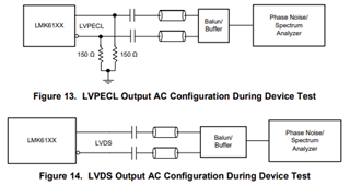
    TLK10232 expects LVDS or LVPECL reference clock, so I believe either of the following designs can be used.

    Best,

    Lucas

  • Thanks, Lucas.

    Just for a final confirmation: There is no need for a DC termination at the Refclk inputs of TLK10232 when driven by LVPECL? Or is there internal termination? The pin list mentiones DVDD as reference but Refclk swing is up to 2000mVpp, so I wonder how the internal circuit looks like.

    Maybe you can find our more about this...

    BR
    Joerg

  • Hi Joerg,

    Judging from LMK61xx datasheet diagrams and TLK10232EVM schematics, I believe termination should be connected as shown in Figure 13 for LVPECL.

    Best,

    Lucas

  • Hi Lucas,

    My question was about DC termination at the inputs of TLK10232 (i.e. behind the coupling capacitors). Could you please confirm that TLK includes all needed components and there is no need for external termination?
    Acc. to our measurements there appears to ba a DC offset of approx. 0.8V on the input pins.

    Thank you...

    BR
    Joerg

  • Hi Joerg,

    That's correct, there is no need for external termination between TLK and AC coupling.

    I'm a bit confused that you see a DC offset of 0.8V at TLK input pins? Shouldn't the AC coupling caps block any DC offset from reaching the input pins?

    Best,

    Lucas

  • Hi Lucas,

    The DC offset results from the internal circuit in the TLK10232. Maybe you can consult the designer of the chip or any detailled documentation to confirm/explain this. It should also be measurable on the EVB w/o much effort.

    Knowing the internal circuit would help to better understand the topic.

    Thank you...

    BR
    Joerg

  • Hi Joerg,

    I understand, thank you for the clarification. Unfortunately this is a legacy device and the original designers are no longer at TI. My recommendation still stands, there is no need for external termination between the TLK and AC coupling capacitors. This is supported by the TLK10232EVM board schematics, which do not include external termination.

    Best,

    Lucas

  • Thanks, Lucas.

    Let's "park" the XO topic for a moment.

    We will start to bring up the KR side of the switches too (based on the available docs we have). Let's see how this progresses and if the FCS issue on the XAUI side is present in this configuration too or other things show up.

    I'll keep you posted.

    BR
    Joerg

  • Hi Joerg,

    Sounds good, thank you for the update.

    Best,

    Lucas