Tool/software:
I want to combine my USB type C female connector to mux and connect it to FFC connector, this is working with USB3.2 in one side only, the other side it's not detecting USB3.2, why is that ?
This thread has been locked.
If you have a related question, please click the "Ask a related question" button in the top right corner. The newly created question will be automatically linked to this question.
Tool/software:
I want to combine my USB type C female connector to mux and connect it to FFC connector, this is working with USB3.2 in one side only, the other side it's not detecting USB3.2, why is that ?
Hello,
In the CC controller, the DIR pin is not getting pulled up, why is that ?
Tried pulling it up externally, then it went to USB3. This was new finding upon testing
Hello,
Looking at the schematic you sent over, one thing I noticed is that you have a 10K resistor for VBUS_DET. We recommend 900KOhm resistors connecting the VBUS, that way VBUS can be detected without potentially hurting the device with higher VBUS voltages.
One other thing I noticed is that there is no pull-up on the DIR line. This is a mistake on my part, I advised that you did not require a pull-up, but you do in fact need a pull-up resistor. In our examples, we use a 10KOhm resistor up to 3.3V. Sorry for the mistake on that on my end.
Another recommendation I have would be to have the ID pin connected to the host or VBUS enable switch in some means, as this can tell the host when the configuration is DFP or UFP, and can communicate when VBUS needs to be sent. For example, when DRP is configured to DFP, the ID pin will pull low, which should tell the host to send VBUS.
Again, sorry for any mistakes.
Thanks,
Ryan
Hello,
Got it, will replace the resistor to 900k.
Yes, we will be making that changes. But again, When pulled up it has same issues, that one side USB3 and on inverting it went to USB2.
And where can the ID pin get connected ?
We do not have an VBUS enable switch, and if connected to host which pin it should be connected to as we have just connectors on both ends.
Thanks
Hello,
And the voltage when CC1 is connected is 0.432V but when CC2 is connected is 4.82V, what does that mean ?
Thanks
Hello,
Got it, will replace the resistor to 900k.
Fixing this resistor may help improve the device performance.
And where can the ID pin get connected ?
We do not have an VBUS enable switch, and if connected to host which pin it should be connected to as we have just connectors on both ends.
If the ID pin can be routed to the host, then you can just connect it to a GPIO on the host, and use that to tell the host when to send VBUS. If you can not route the ID pin to the host, you may need a VBUS switch.
Needing to tell the host to send VBUS is specifically a DFP requirement. This E2E FAQ provides more information on how to control VBUS: https://e2e.ti.com/support/interface-group/interface/f/interface-forum/1324014/faq-how-to-control-vbus-on-a-usb-c-port
Yes, we will be making that changes. But again, When pulled up it has same issues, that one side USB3 and on inverting it went to USB2.
Pulling up the DIR pin does not help to improve USB3 performance in either orientation?
Tried pulling it up externally, then it went to USB3. This was new finding upon testing
This previous message made it sound like pulling it up resolved it.
And the voltage when CC1 is connected is 0.432V but when CC2 is connected is 4.82V, what does that mean ?
Typically, this just means that the host is pulling one line up, while the device is pulling one line down. It indicates a connection has been made.
Thanks,
Ryan
Hello,
No, it's not able to route to host. There's no space to add vbus switch.
It detects in one direction in which in which it was not detecting USB3. But the one in where USB3 was working shows as USB2 after pulling it up.
Hello,
No, it's not able to route to host. There's no space to add vbus switch.
VBUS does need to be controlled in some way to ensure that VBUS is not being sent until AFTER CC negotiation is complete, as noted in the FAQ I sent previously. It does not have to be one of the methods mentioned above, but it does need to be controlled.
It detects in one direction in which in which it was not detecting USB3. But the one in where USB3 was working shows as USB2 after pulling it up.
Would it be possible to measure the voltage of the DIR pin to ensure it is changing, or if it is staying at one voltage no matter the cable orientation?
Thanks,
Ryan
Hello,
Pulled the DIR to 3.3V using 10k, the port identified as USB2 got identified as USB3, but previously which was getting identified as USB3 is showing USB2 now, Why is that ?
Pulled up is done on the trace from DIR to SEL pin.
Noticed one more,
One side inserted, CC1 voltage is 0.432 V and CC2 is 0.05V.
Other side inserted CC1 voltage is 0.432V and CC2 is 0.432v
Hello,
It looks like the DIR pin is not actually changing direction regardless of the cables orientation, which sounds like the CC negotiation is not being completed. This typically happens when VBUS is not controlled within the USB type-C spec for CC negotiation.
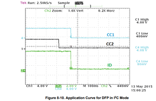
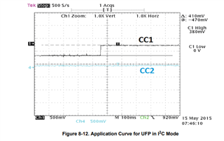
If you could take some waveform measurements of the CC pins to see if this negotiation is taking place, or if it is similar to what we have in our datasheet, that would be good to check as well.


Thanks,
Ryan
Hello,
Sorry, it was:
One side inserted, CC1 voltage is 0.432 V and CC2 is 0.0V.
Other side inserted CC1 voltage is 0V and CC2 is 0.432V
https://www.ti.com/lit/df/tidrk35/tidrk35.pdf?ts=1738245790770
This is a reference from TI itself, the SEL is not pulled up.
Hello,
Got it, that's a bit closer to what I would expect, one side high while the other is pulled low. However, without CC negotiation taking place, it's likely that regardless of the CC pin levels, the situation of one side being USB3 recognizable while the other only does USB2 will not change, as since there is no CC pin negotiation, there is no way for the CC controller to properly communicate to the mux via the DIR pin what orientation the Type-C cable is in so that the mux can switch.
https://www.ti.com/lit/df/tidrk35/tidrk35.pdf?ts=1738245790770
This is a reference from TI itself, the SEL is not pulled up.
This is likely an error made in the design back in 2015. Thanks for pointing it out, I will see about getting it updated.
Where are you measuring the CC pin voltages? At the CC controller, or the UFP device/source of the CC pins? Would it be possible to monitor the waveforms of the CC pins to see if there is any negotiation or just a flat value? Is there no way to control VBUS?
Thanks,
Ryan
Hello,
The CC pins were monitored on both sides, it was same. We tried pulling it up using 10k once more, then USB3 got identified on inverted and normal too. Maybe it was a soldering issue on the first time.
Sorry for the misinformation.
Hello,
Understood, so then is the issue solved? Can you detect USB3 regardless of the orientation of the type-c cable?
Thanks,
Ryan
Hello,
Yes, sorry for the delay. Yes the issue is solved. USB3 is detecting regardless of the orientation of the cable.