DP83869HM: DP83869 Accessing with MSP-EXP430G2ET

Part Number: DP83869HM
Other Parts Discussed in Thread: USB-2-MDIO, MSP-EXP430G2ET, DP83869, MSP430F5529, DP83869EVM

Tool/software:

Hi,

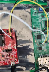
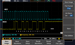
We are trying to access the DP83869 PHY with MSP-EXP430G2ET board by connecting MDC, MDIO lines as per the USB-2-MDIO Document. 

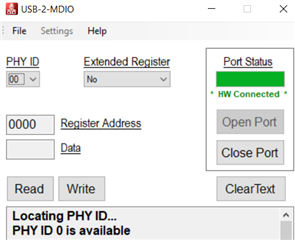
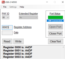
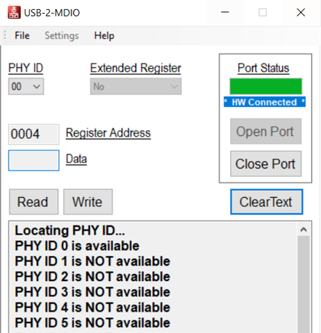
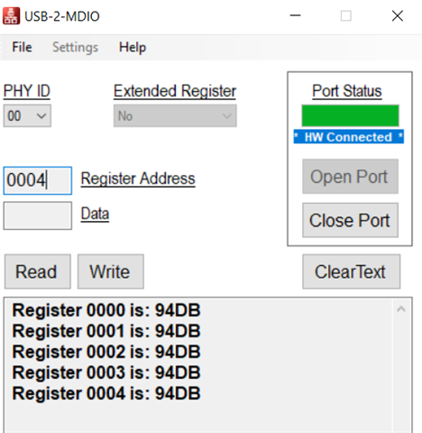
Our PHY ID is 0000. But while trying with the USB-2-MDIO tool, we are getting all 32 phy's are available, but we are not able to read any specific register.

We are getting values as FFFF


Please help us to access the DP83869 with MSP-EXP430G2ET Board. The schematics file is attached.

Regards

Guru sai prasanth A


DP83869_Texas.pdf

  • Hello,

    I would recommend using a MSP430F5529 launchpad instead of MSP430G2. Most of our modern EVMs solely use the MSP430F chip. Once this board is obtained and is flashed, we can look to continue discussion.

    Sincerely,

    Gerome

  • Hello, 

    We are using M430F5528 chipset present in MSP-EXP430G2ET Launch pad. With this can we able to access the DP83869 because previously we have accessed in another product. 

    Regards

    Guru

  • Hi Guru,

    I believe the target device is the G2553, which is different than the F5529 that is present on the MSP430F5529-LP. We can look to inquire about this, but I would recommend using MSP430F5529-LP.

    Could you please share the connection scheme from launchpad to PHY, as well as the powerup sequence? Has the DUT been flashed with the USB2MDIO firmware?

    Sincerely,

    Gerome

  • Hello,

    Now are able to detect the PHY DP83869 as shown in the below image.

    But when we read any register, its returning only one value for all the registers.

    Please help me out for reading the registers.

    Please find the attached schematics

    Rework done : R442 is pull down for configuring in RGMII to Fiber 1000M mode

     EPCB-5049-O-00 - texas query.pdf

    Regards

    Guru 

  • Hi Guru,

    I am very curious as to the readbacks shown. Can you please share photo of the setup from launchpad to DUT?

    Sincerely,

    Gerome

  • Hello,

    As we referred the MSP430 Flasher guide document, P1.4 (MDC) & P1.5(MDIO) Connected to DP83869 MDC, MDIO Pins, Ground also we have connected accordingly.

    Regards

    Guru

  • Hello Guru,

    As I have mentioned before, I am not familiar with using USB2MDIO with the MSPG2 launchpad; only MSP430F5529 launchpad. To continue support, I would recommend switching to using this launchpad. Else, the only other suggestion I can recommend is to try switching MDC and MDIO around and re-read for expected value.

    Sincerely,

    Gerome

  • Hello,

    Sorry for the late reply. Meanwhile we have procured the MSP430F5529  launchpad.

    We tried reading the DP83869 PHY, we are getting the same value : 94DB For all the registers.

    We are able to read other PHY's (like VSC8211 with the same board without any errors)

    As recommended, we have swapped the MDC, MDIO lines. In that case PHY 0 is also not detecting.

    Please guide us to read the DP83869 PHY with new board. 

    Regards

    Guru

  • Hi Guru,

    This is very strange. I would still not expect this behavior even when operating with MSP430F5529 LP. If you are seeing this error only on this board, I would like to request that you do an ABA swap of the device. Please note that MDC does not require a PU. 

    Are all boards produced showing this issue? How many are there?

    Sincerely,

    Gerome

  • Hi Gerome,

    I would like to request that you do an ABA swap of the device.

    We have checked in all boards. The same issue exists in all cards.

    Please note that MDC does not require a PU.

    In multiple boards we have implemented, so as standard we have implemented. We have removed and checked but still same issue.

    We are following attached document for flashing the MSP430F5529 LP.

    MSP430 Flasher guide.pdf

    Regards,

    Guru

  • Hi Guru,

    In case, could you please flash the launchpad using this FW? This will still allow for USB2MDIO functionality, but will be standard with what TI has in their labs.

    I am also curious if you have a DP83869EVM or other TI EVM where MDC/MDIO connections are available. I want to root out if the launchpad is showing issues vs the hardware design may be a concern.

    Sincerely,

    Gerome

  • Hi Gerome,

    We don't have DP83869EVM or other TI EVM

    We have double checked the voltages 3.3V, 2.5V. 1.1V. All are getting exactly.

    Also we have checked the CLK_OUT (Pin 40) : which is 25Mhz

    The launchpad working fine, because we are able to read to other PHYs (VSC8211)  which is in the same board.

    Regards

    Guru

  • Hi Guru,

    Thanks for the information. It is unclear why the PHY would return the same value for all registers if there isn't a gross failure. Other than register access, is the PHY able to get SGMII link and have clean throughput communication? This would be able to help determine if the PHY is in a gross state of misbehavior. This can be obtained through more application/system-based checks such as LED indication, link partner communication, MAC status. Since the device is supposed to be in RGMII/SGMII bridge, having the RGMII bus be at certain frequencies (depending on speeds) is a telltale sign of functionality. 

    I would also like to see from a scope level the MDC/MDIO communication. Is it possible to provide an annotated scopeshot of the MDC/MDIO communication when returning the 0x94DB value? This will help rule out signal integrity issues.

    I have also attached the MSP FW from last post. This can be flashed using Uniflash.

    8037.msp430-usb-to-mdio-universal-v3.04.txt

    Sincerely,

    Gerome

  • Hi Gerome,

    PHY is not able to get the SGMII link, NO LED indication, NO link partner communication.

    Please find the below waveform of MDC, MDIO data for 0x94DB.

    Regards

    Guru

  • Hi Guru,

    Thanks for the information. I would like to change the approach now that the observation reported is a gross failure. I would like to check that the power up sequence and the strapping look good from both an electrical side.

    Could you please provide screenshots of the following:

    1) All power rails, Reset_N, PWDN

    2) Reset_N, all strap pins upon Reset_N deassertion

    Could you also provide a picture of the top marking of the DP83869 device you have on your board?

    Sincerely,

    Gerome

  • Hi Gerome,

    Please find the waveforms in the attached document.

    For the JTAG_TDO pin, as per the strapping & hardware connections, we should get 3.3V, but we are getting 0.063V.

    DP83869_debugging.docx

    Please find the top marking of DP83869 device in our board.

    Regards

    Guru