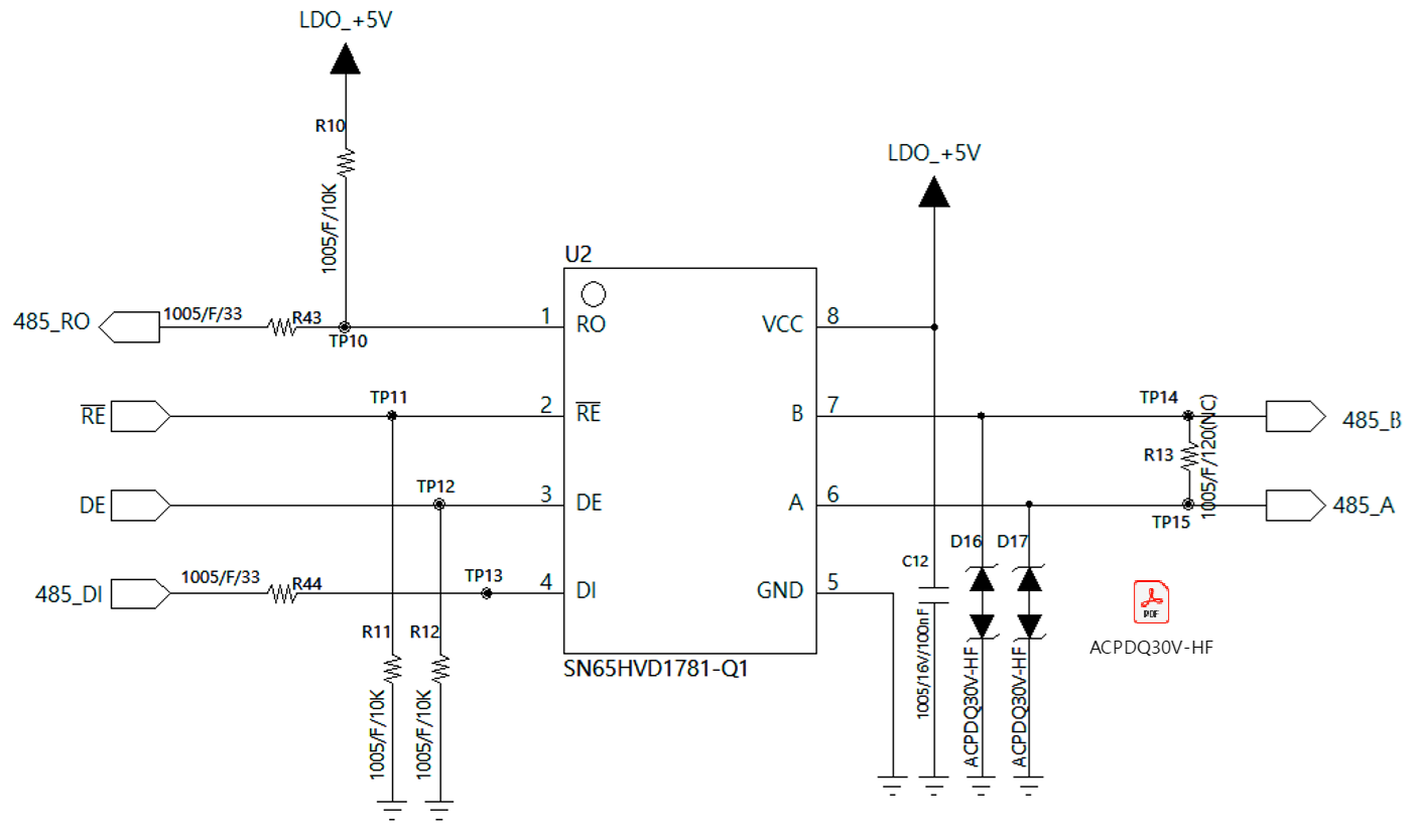
Tool/software:
Dear TI experts,
My customer drew their schematic with SN65HVD1781-Q1.
Could you review the schematic?
Best regards,
Chase
This thread has been locked.
If you have a related question, please click the "Ask a related question" button in the top right corner. The newly created question will be automatically linked to this question.
Tool/software:
Dear TI experts,
My customer drew their schematic with SN65HVD1781-Q1.
Could you review the schematic?
Best regards,
Chase
Hi Chase,
My only comment is that it looks like the 485_TXD and 485_RXD net labels are swapped. Typically DI "Driver input" is connected to TXD and RO "Receiver output" is connected to RXD. You can use this schematic review as a reference: https://e2e.ti.com/support/interface-group/interface/f/interface-forum/1057571/sn65hvd1781-sch-review
As long as the customer is aware of the labeling, the rest of the schematic shown looks good.
Best,
Ethan
Dear Ethan,
Thank you for your support.
My customer wants to review modified schematic. Please check new schematic below.
- Is it okay to use D16 and D17?
- Is it okay to use R43 and R44?
Please check this issue. Thanks.
Best regards,
Chase
The diodes are OK. But in general, protection components should be as near the connector as possible, while the termination resistor should be as near the transceiver (at the end of the bus) as possible.
A source termination resistor should be near the output pin of the driving device. R43 is near the RO pin, but R44 should be near the controller's TXD pin.
I agree with Clemens' points here. ESD protection diodes should be placed after the termination resistor and as close to the external connector as possible.
Dear Clemens, Ethan,
Thank you for your support. I will discuss it with my customer and reply if I have more questions.
Best regards,
Chase
Dear Ethan,
Hope you have a good day.
My customer asked that it is okay to use ESD diode on pin 6 and pin 7 below. Could you check that it is okay or not?
Best regards,
Chase
The working voltage must be large enough for all voltages that actually can happen on the bus. This transceiver supports −7 V … 12 V, which is based on 0 V … 5 V with a ground shift of up to ±7 V between nodes. If the ground shift in your application cannot be that high, you can use ESD diodes with a lower working voltage.
Hi Chase,
Thanks for sharing the datasheet. I would recommend a working voltage of 12V instead of 5V, which Clemens explains well. I might recommend ESDS552 as TI's RS-485 ESD diode. It is a 2 channel device (so only one is needed for RS485) with 30kV IEC contact/airgap, 25A surge, and 12V VRWM. If low capacitance is a requirement, our Protection Devices team can provide more assistance to suit their needs. If that would be helpful, just let me know and I can transfer this thread over to them.
If the customer is ok with the diode clamping past 5V, then that diode is acceptable.
Let us know if you have any further questions!
-Ethan