This thread has been locked.

If you have a related question, please click the "Ask a related question" button in the top right corner. The newly created question will be automatically linked to this question.

DP83869HM: DP83869HM not initiating any auto negatition pulse and dont see any lights glowing on RJ45 also

Part Number: DP83869HM
Other Parts Discussed in Thread: AM2634, , DP83869, TMDSCNCD263, DP8386X-ASPEED-EVM

Tool/software:

Hi Team,

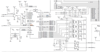
We have used DP83869HM and AM2634 controller to test ethernet. We have referred of AM2634 PROC_A to design our PCB. We are able to donwload code into AM2634 using JTAG probe.

We are testing ethernet part. So far we have checked below things.

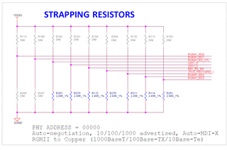
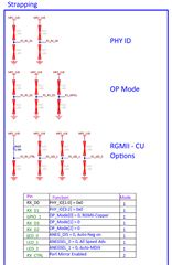
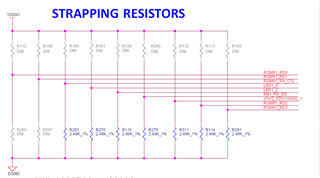
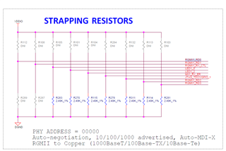
  1. Strap resistor setting for PHY address:

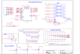
            We have connected same way as AM2634 PROC A schematic. as shown below. Please verify.

2. We have mesured RBIAS voltage:  300mv

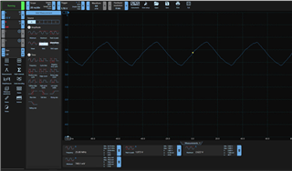
3. XI clock input to IC

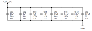
4. We are providing 1.1V, 2.5V and 3.3V from external power supply. Currently I am manually switching on/off both supplies. We are supplying 1.1V and 2.5V first then within 1 sec 3.3V. Supply

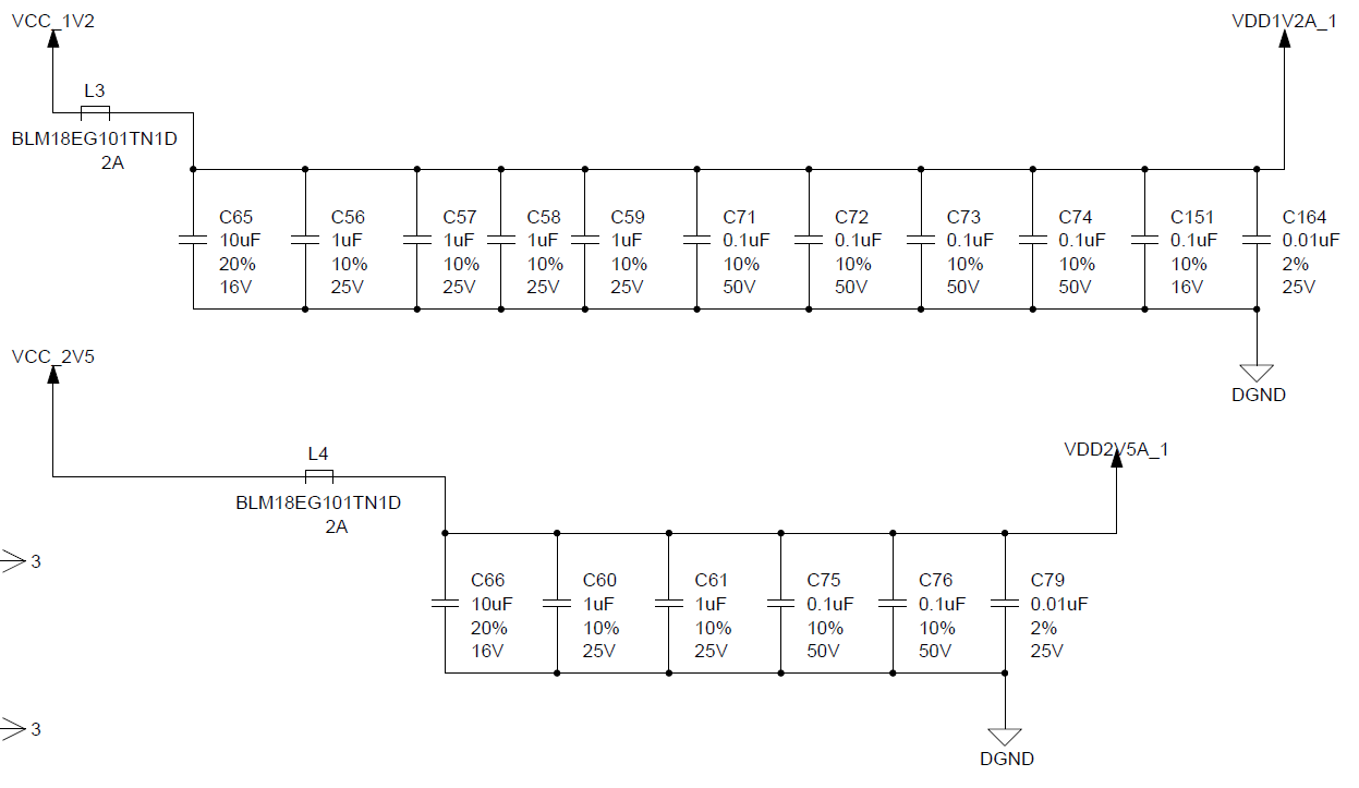
But as per datasheet it shows 2.5 is analog supply and 1.1V should be digital supply. I did not understand this. We are providing both supplies from external power supply

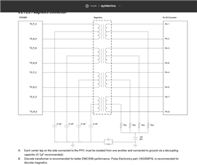
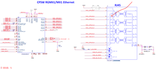
5. DP83869HM IC connections

Both Earth ground and DGND are not shorted

6. We have not programmed any SW in AM2634 yet for Ethernet. Without SW also LEDs should respond

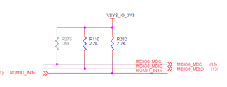
7. MDIO and MDC setting as below

8. We have also changed and mounted new DP83869HM IC. But still not working

Currently, I am stuck with this. Dont have any clue on how to debug futher. This is very important for our project mlestone.

Thanks!

  • Hi,

    1. When operating in the three supply configuration, our recommendation is to power all supplies together. If powering all supplies simultaneously is not possible, then power VDD1P1 and VDD2P5 first with VDDIO and VDD1P8 following within 50rms.

    2. The DC voltage across the RBIAS resistor should be 1V. How are you measuring the 300mV at RBIAS? Can you power down the board and verify the RBIAS resistor value is 11k +/- 1%?

    3. Can you also read DP83869 register 0x6E? I want to confirm the device is programmed with the correct operational mode. Please note the registers 0x6E are extended registers and cannot be accessed directly. 

    Thanks

    David 

  • Hi David,

    1. I am using two supply method. I am not providing 1.8V
    2. I have powered up and checked RBIAS resistor value is 11K but voltage is very less than 1V. I have measured it across RBIAS by using TP2 as shown above.
    3. Please let me know how to to read 0x6E register? Do I need to read it using AM2634 controller? If yes then please let me know how can I do that?

    Thanks!

  • Hi,

    To read a register in the extended register set:

    1. Write the value 0x001F (address function field = 00, DEVAD = 31) to register REGCR.

    2. Write the desired register address to register ADDAR.

    3. Write the value 0x401F (data, no post increment function field = 01, DEVAD = 31) to register REGCR

    4. Read the content of the desired extended register set register to register ADDAR.

    With two supply method, you still want to power up all supplies together. If powering all supplies simultaneously is not possible, then power VDDA2P5 and VDD1P1 first with VDDIO following within 50ms.

    Also looking at the schematic, I noticed that you are using center tap shorted magnetic. With the center taps shorted, we have seen link instability issues. You need to use a magnetic, such as HX5008FNL, to configure the center taps such that they are separately decoupled to GND as shown in the datasheet. Please also see this E2E FAQ for the magnetic selection, https://e2e.ti.com/support/interface-group/interface/f/interface-forum/1161575/faq-dp83867e-how-do-i-choose-magnetics-for-my-industrial-phy

    Thanks

    David

  • Hi,

    How should write values to registers. Do I need to control this using AM2634. Do you have any example or steps?

    Thanks!

  • Hi Ajit,

    Could you please confirm which SDK is planned for use? AM2634 can access the registers - however this will require a specific example from SDK and tinkering with register read/write functions from the example.

    If programming and tuning a specific example from SDK is not possible, a simpler alternative is using another controller (e.g. MSP430F5529 Launchpad) with MDC/MDIO pins connected to PHY, and USB-2-MDIO GUI for register access.

    Thank you,

    Evan

  • Hi Evan,

    I am using mcu_plus_sdk_am263x_10_01_00_31 SDK.

    Thanks!

  • Hi Ajit,

    I am not able to find an example using register access in this SDK, but please see this API reference for MDIO functions:

    https://software-dl.ti.com/mcu-plus-sdk/esd/AM263X/09_00_00_33/exports/docs/api_guide_am263x/DRIVERS_MDIO_PAGE.html

    Please let us know if there any challenges when using these functions for register access.

    Thank you,

    Evan

  • Hi Evan,

    Thanks! Let me try to use this API. I will let you know.

    Meanwhile, can you please help understand why do we need to provide 1.1V digital and 2.5 Analog? 

    Can I provide both using external DC power supply directly at power supply circuits mentioned above?

    Thanks!

  • Ajit

    The 1.1V provides power to the DP83869HM digital portion of the circuit while the 2.5V provides power to the DP83869HM analog portion of the circuit. Any DC power supply can be used to supply power to the 1.1V and 2.5V as long as the proper voltage level and sequence requirement is met. For the 2.5V analog, please make sure you are connecting 0.1-µF, 1-µF ceramic decoupling capacitors near each pin.

    Did you also get a chance to replace the center tap shorted transformer?

    Thanks
    David

  • Thanks David!

    We are making circuit to supply 1.1V and 2.5V together then 3.3V within 50ms. 

    I have not understood about magnetics of RJ45, Can you please explain more with diagram (if any)? How can I change magnetics? I have used same part no of RJ45 as mentioned in AM2634 proc card schematic page no 12 as below.

  • Ajit

    I am referring to the magnetic being used in the design which the center tap are being shorted together as shown below.

    We recommend to use a magnetic, such as HX5008FNL, to configure the center taps such that they are separately decoupled to GND.

    Thanks

    David

  • Hi David,

    Yes, I just referred DP83869HM datasheet. Its mentioned in that.

    However, when I checked schematic of  TMDSCNCD263 (Control Card of AM2634) from TI. I found that it has used  LPJG16314A4NL as shown on page no. 12.

    Please review it and let me know if any compatible part number of RJ45 that I can use for DP83869HM

    Thanks!

  • Hi Ajit

    You can use Wurth Elektronik 7499111000A RJ45 Magjack Connector. This component has been used on the DP83867 EVM in the past so we have a history of validating our parts with it.

    Thanks

    David

  • Hi David,

    Thanks! I will use above RJ45 for DP83869. 

    At present, I am able to get RBIAS of 1V and clock out on pin 40 is also good. So, I think DP83869HM is responding okay. 

    However, still I can not get LEDs on RJ45 glowing.

    I am confused with Strap resistor setting for below mode.

    PHY ADDRESS = 00000
    Auto-negotiation, 10/100/1000 advertised, Auto-MDI-X
    RGMII to Copper (1000BaseT/100Base-TX/10Base-Te)

    1. Schematic of  TMDSCNCD263 (Control Card of AM2634) shows below setting:

    2. DP8386X-ASPEED-EVM schematic shows below setting:

    Why so different? 

    My board current strap resistor setting is like below.

  • Hi Ajit

    The strap setting between the TMDSCNCD263 and the DP8386X-ASPEED-EVM is functionally the same. The DP83869HM uses many of the functional pins as strap options to place the device into specific modes of operation. The values of these pins are sampled at power up or hard reset. As you can see from below, these pins have pulldown enabled during reset, so the pin strap will register as "0" in either case of DNP or external pulldown.

    There are the LED functions in RGMII to Cooper mode: 

    If none of these LEDs are blinking, then I suspect the link is failing. Have you been able to validate the register access to confirm the link is up?

    Thanks

    David

  • Hi David,

    Sure let me check if I can use API mentioned above to check register access. 

    Meanwhile, do we have EVM board or module with RJ45 and DP83869 IC? So that I can use it to connect to my board by connecting signals coming from AM2634 from my board to this EVM board. This will save a lot our prototype development time.

    Thanks!

  • Hi, Ajit

    Can you use the DP83869HM EVM as a possible solution, https://www.ti.com/lit/ug/snlu237a/snlu237a.pdf? The RGMII/MII INTERFACE goes out to a header on the EVM which you can use to connect to the AM2634.

    Thanks

    David  

  • Hi,

    I will go ahead and close this E2E thread since there has been no activity. You can re-open this E2E thread by responding to it.

    Thanks

    David