This thread has been locked.

If you have a related question, please click the "Ask a related question" button in the top right corner. The newly created question will be automatically linked to this question.

SN65HVD1477: SN65HVD1477DGKR

Part Number: SN65HVD1477
Other Parts Discussed in Thread: AM26LV32E, AM26LV31E, DS90LV012A, DS90LV019, DS90LV011A

Tool/software:

Hi,

My understanding is, the primary difference between RS-422 and RS-485, apart from the number of drivers (RS-422 have 1 driver, while RS-485 supports multiple drivers), lies in their wiring configuration. RS-422 employs a 4-wire setup with two differential pairs—one for transmission (Tx) and one for reception (Rx)—allowing for full-duplex communication. In contrast, RS-485 generally uses a 2-wire system with a single differential pair for half-duplex communication, though it can also be configured for full-duplex with a 4-wire setup.

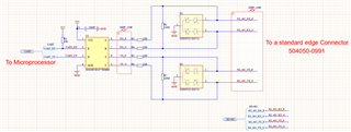
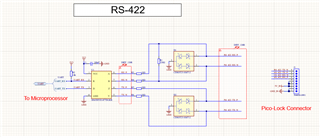
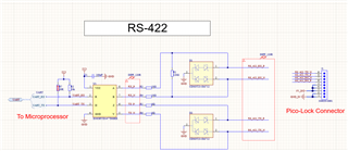
I reviewed the datasheet SN65HVD1477, and the term RS-422 is only mentioned once. Could you confirm if the schematic I have is indeed configured for full-duplex RS-422? If not, what adjustments should I make to the schematic to ensure it meets RS-422 standards? Additionally, would I need a connector specifically designed for differential pairs, or would any connector suffice (Please note, the RS-422 transmission occurs within 30 cm between two boards.)? I am currently using the Molex Picolock connector (https://www.molex.com/en-us/products/part-detail/5040500991).

Thank you

Regards,

Kavin

  • The RS-422 and RS-485 specifications do not actually specifiy many details about the exact wiring. There are some small differences in the electrical characteristics, but RS-485 transceivers are fully backwards compatible with RS-422, so the difference between calling a device "RS-485" or "RS-422" is often ignored in practice.

    If you have a half-duplex bus, use a half-duplex transceiver. If you have two signals, one in each direction, you must use a full-duplex transceiver. There are applications where more than one signal in one direction is needed; for those, there are multichannel devices, e.g., AM26LV31E/AM26LV32E.

    The RS-4xx specifications do not say anything about connectors. Use whatever works.

    The termination resistor should match the characteristic impedance of the cable. For a unidirectional signal, termination is needed only at the receiver, and should be omitted at the driver to reduce the load. Otherwise, the schematic looks OK.

    For short distances, LVDS is a low-power alternative that allows higher data rates (see, e.g., DS90LV019, or DS90LV011A+DS90LV012A).

  • Hi Kavin,

    Clemens comments are correct.

    Just to add though, with RS422 we typically see only one termination resistor which is populated at the furthest point from the driver (on the receiver node). In RS485 with half duplex set up, there is generally 2 termination resistors, one one the two furthest away points of the bus. 

    So if you're planning on using full duplex, your schematic Z/Y pins technically don't need the termination resistor there. The 10 ohm resistors will also affect the performance a little since they will look like a voltage divider to the end termination resistor on the receiver side.

    -Bobby

  • Thank you, Clamen and Bobby, for the detailed explanation. As you advised, I have removed the 120-ohm termination resistor on the transmitter side since we are aiming for full-duplex. We will use the current connector and observe its behavior. Please let me know if I should remove the 10-ohm resistor on the receiver side, pins A and B.

    Regards,

    Kavin

  • Hi Kavin,

    I don't think you need the 10 ohm resistors on the transmitting side (pins Y and Z). If you want to, you can change them to 0 ohm and make them 10 ohms later if you really do think you need them.

    One other minor suggestion is I usually tell customers to also put a pull up resistor on the D pin in the case that the MCU/processor powers up with their TX pin in a high-Z state. Having a pull up resistor on D can ensure the state if the MCU/processor hasn't set TX to a logic high yet. You can set this pull up resistor to be a do not populate, having it weak at around 20k would probably be fine. 

    -Bobby

  • Hi Bobby,

    Thank you for your prompt response.

    Please find attached the final schematics. I'll let you know how it behaves as soon as we test the board.

    Kavin

  • Hi Kavin,

    This looks fine to me.

    One other thing that may be helpful. You can add external fail safe biasing resistors on the receiver pins (A/B). This isn't required since this device has internal fail safe biasing (Vth+ is negative) but for added margin you can include external fail safe resistors. Also a do not populate situation where you can populate them if you see noise on the bus that causes glitches on the receiver. 

    This is just a simple pull up resistor on A and pull down resistor on B. (again optional but always nice to have when you do need it).

    -Bobby