This thread has been locked.

If you have a related question, please click the "Ask a related question" button in the top right corner. The newly created question will be automatically linked to this question.

THVD9491-SEP: Inverting positive and negative to A and B inputs

Part Number: THVD9491-SEP

Tool/software:

Hi Team,

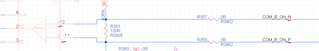
We have a logic problem we would like to solve by connecting the positive line to B and the negative line to A, see below: 

So when I look the this table:

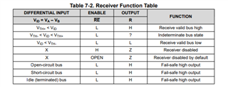
If the transceiver will transmit '1' the output in R is '0' and when it will transmit '0' then R output is '1' and in Idle it is '1' also?
Would you say that is a valid thing to do?

Thanks,

Moral.

  • The idle output is high because that is the idle state of a UART logic signal.

    What is the actual problem you're trying to solve? If you want to receive an inverted signal and the idle state to be low, then connecte the A/B lines normally and add an inverter at the R pin.

  • Hi Clemens Ladisch,

    Thanks for the quick respond!
    Inverter will not help, here is why.

    In my system we have master and slave, the master transmitting in RS485 '1' (which means slave can transmit back on another line) and '0' (which means don't transmit on the other line to avoid damage to the master)

    This is the logic we got and now the problem is that 'Idle' and '1' both seems like it is ok to transmit from slave to master (thus inverter on R wont help distinguish between '1' and 'Idle')  and that can cause damage to the master.

    We cant change the logic from the master so we thought we can change it in the slave by connecting the P and N opposite and on the slave the logic is '0' is ok to transmit and '1' / 'Idle' is don't transmit on the other line.

    So my question is if we will connect it in reverse way (RS485_signal_P to B and RS485_signal_N to A) - will it work?

    Thanks,
    Moral.

  • Add fail-safe resistors (like R359/R360) to pull A and B to the desired idle voltage.

  • Hi Moral,

    As Clemens has pointed out, you can populate pull up and pull down resistors on the A/B pins to set a known bias state. Adding a pull up resistor to B and a pull down to A will make R output low when it is idle. If you want to do the opposite logic for idle, then make the pull up resistor on A and pull down on B. You can try 1k resistors. 

    -Bobby