This thread has been locked.

If you have a related question, please click the "Ask a related question" button in the top right corner. The newly created question will be automatically linked to this question.

DP83826I: Capacitor on CEXT pin: Recommendations and Requirements

Part Number: DP83826I
Other Parts Discussed in Thread: DP83826E, DP83826EVM, HSEC180ADAPEVM

Tool/software:

Hello,

I am looking for guidance on CEXT capacitor on the DP83826I and DP83826E.

This old thread came as an authoritative answers:
https://e2e.ti.com/support/interface-group/interface/f/interface-forum/935079/dp83826i-dp83826-cap-on-cext-pin

However, here are the contradictions:

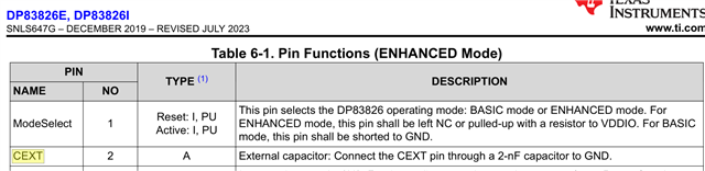
1- Datasheet States: External capacitor: Connect the CEXT pin through a 2-nF capacitor to GND.
Note this is the only mention of CEXT in the whole datasheet.

2- DP83826EVM uses a 0.1uF capacitor instead of 2nF.
From SNLU262A – DECEMBER 2019 – REVISED JUNE 2023. Figure 6-2 and Table 7-1.
www.ti.com/.../SNLU262


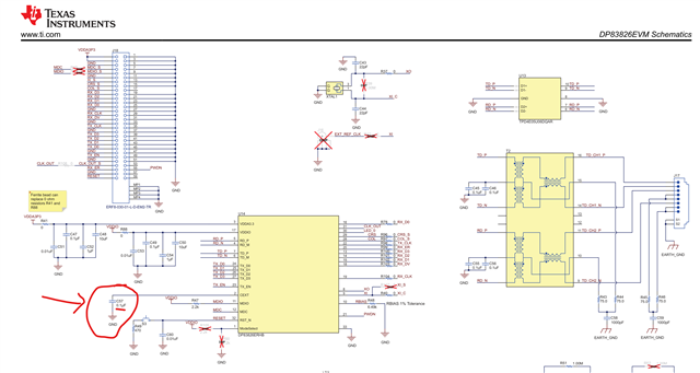
3- EtherCAT app note uses 2.2uF+0.1uF instead of 2nF.
Application Note: How and Why to Use the DP83826 for EtherCAT Applications
SNLA344C – MARCH 2022 – REVISED OCTOBER 2023
https://www.ti.com/lit/pdf/SNLA344
Figure 3-1
Note this is the only time an explanation is given: Network used for further margin on EMI performance

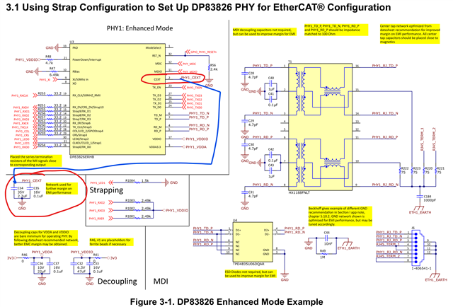
4- HSEC180ADAPEVM uses 2.2uF+0.1uF
This board docks the C2000 we are evaluation, and includes 2x DP83826E for EtherCAT communication.
From HSEC180ADAPEVM Design Files Package
https://www.ti.com/lit/zip/spac002
MCU134A_SCH.pdf
Sheet 7 of 13 and 8 of 13.
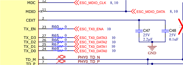
=====

The questions are:

1- Is the 2nF recommendation still valid?
5 year old referrenced questions stated putting 1uF on the EVM was an error and will be corrected. I now see TI doubled-down on extra capacitance.
A range instead of a value would help a lot.

2- What is CEXT for, exactly?
Knowing the function would help designers make adequate adaptations

3- Is there real EMC concerns for this pin?
As suggested by the EtherCAT app note. Knowing the expected frequencies would be required to properly build a capacitive network.

If designers are using their own judgement to deviate from datasheet, without adverse effects, then it should not be such a big deal. However, seeing ALL the TI physical realisations so far away from the recommendation puzzles me, a lot.


 & : Did your design work out good with 2nF? Any notable troubles in EMC?
: Did the situation change since your last answer?

Thanks!

  • Hi Jerome, 

    I understand your confusion.Unfortunately, I cannot comment on the internal function of CEXT pin since it is proprietary TI information

    The recommendation of 2nF capacitance is valid. This capacitance is required for the device to be functional, however, after additional testing, we found that certain other capacitor values, such as the ones found in the EtherCAT app note, help in improving the EMI performance margin. These capacitors are not required for functionality, but a placeholder can be kept to add these capacitors if the extra margin is needed since they are optional.

    There are no additional EMC concerns, the PHY would function fine with only the 2nF cap.

    Best,

    Vivaan

  • Hi Vivaan,

    Let me rephrase your answer:

    CEXT requires a capacitor GND.
    Value is minimum 2nF
    Recommended is 0.1uF (as the DP83826EVM is the only one with EMC test results shown in the user manual)
    Maximum is above 2.3uF (as proven by the various EVMs)
    More capacitance is better for EMC, but the effects and real maximum is a secret.

    >> however, after additional testing, we found that certain other capacitor values, such as the ones found in the EtherCAT app note, help in improving the EMI performance margin

    Can you share those additional test and results?

    Please, help me better understand the implications of this. I want to purchase your PHYs and design with confidence, not book extra runs at the lab in case I need to populate a wasteful empty footprint.

    Respectfully,
    -Jerome

  • Hi Jerome, 

    There is no minimum and maximum recommended values like you are suggesting. The recommended value is 2nF, not a range between 2nF to 2.2uF. We utilized the additional capacitors to increase the margin for EMI. These are not required. 

    I believe there may be some miscommunication. You do not need to place an empty footprint, it is an optional addition that you have the choice to enable, if additional EMI margin is needed. The PHY will be able to perform without these additional capacitors, with only the recommended 2nF. 

    Best,

    Vivaan

  • Thanks Vivaan,

    I'm really interested in those "margins".

    Do you have EMI results you can share? A graph or summary? How much gain at what frequencies?

    It's again hard to follow the recommended 2nF when TI uses 50x to 2200x the recommended values on 3 out of 3 boards.
    Should I use 2.2uF myself?

  • Hi Jerome, 

    The information you are requesting is not public information, I cannot provide internal lab reports.

    The recommendation in the datasheet should be followed for proper functioning of the device, and the optional 0.1uF/2.2uF capacitors can be used for additional performance. 

    Best,

    Vivaan