


Part Number: DS90UB954-Q1
Other Parts Discussed in Thread: ALP
Tool/software:
Hi TI team,
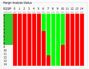
Currently we have carried out the MAP analysis for our target board deserializer and serializer(3 variants). We are seeing for one variant the results are and for another variant the results are fail. Below are the results.
Variant 1:
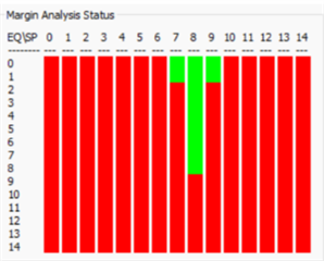
Variant 2:

Variant 3:
We have below questions:
1. We are not able to get the same results for the same setup. Can we consider this is as an issue with the ALP tool?
2. For our variant 2 and 3 we are seeing that the results are not meeting the pass criteria, can you please let me know how to start the debugging for these failures(currently we have reduced the cable length and checked the performance, still the performance remains the same)
3. Need to know whether these results holds good for the forward channel alone or for the back channel also(because the FPD link support bidirectional communication)
4. Is it must to run the EQ and SP settings for the full scale or can we do it for a shorter range, current issue that we are seeing is none of the EQ settings above 7 are able to get 4 consecutive SP settings as pass.
5. Is there any need to modify the register settings in actual scenario based on these link margin results? If we need to modify what is the process?

