Tool/software:
Hi expert
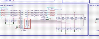
since we can't test both RX and TX, can we use the same parameter at this two channel?

This thread has been locked.
If you have a related question, please click the "Ask a related question" button in the top right corner. The newly created question will be automatically linked to this question.
Tool/software:
Hi expert
since we can't test both RX and TX, can we use the same parameter at this two channel?

Hi Feeney,
Typically, it is better to have both lanes tuned to match the expected loss in the signal path. If the customer cannot test or calculate this loss, they could theoretically use the same settings for both lanes. However, if the customer sees issues with redriver/signal quality, they may need to adjust the values of these config pins to better match the systems needs.
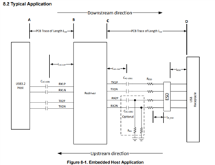
A few notes, based on this schematic you provided. I see RX lanes have 100nF caps on both sides. Assuming the signal is already being coupled from the device side, the capacitors on the FFC side of the redriver should not be necessary. Something like this diagram is what we would expect for this ac coupling caps:

And for configuring the OS pins, these need to be either pulled-up or pulled-down. They should not be left floating.
Please let me know if there are any other questions.
Thanks,
Ryan
Hi Feeney,
In that review, he said the 100nF was only needed for the TX pins/lane. He also states that the RX lane needs to have 330nF capacitors if they are being used, not 100nF capacitors. C1B10 and C1B11 are connected to the RX lanes of the USB3 signal, so if the customer intend to have AC coupling caps near the redriver like this, they need to be 330nF. Otherwise, the capacitance on the line will go below what is allowed in the USB3 spec.
If the customer wanted to, they could also just remove the caps there and not worry about it. 330nF caps are typically used for ensuring the signal stays in a compliant capacitance range, but are not required.
Thanks,
Ryan
Hi Ryan
Thank you. one more question, if remove the 330nF, do we need keep the Rrx on board?
Hi Feeney,

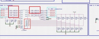
For this schematic, only the capacitors highlighted by the red square above should be required. C1B10 and C1B11 are not required, and can be either removed or changed to 330nF. These capacitors should only be 100nF if there is not already AC coupling on these lines, which there should be on the other side of the FFC connector.
do we need keep the Rrx on board?
Are you referring to the RX lines in general, or the capacitors on the SOC side? The capacitors on the SOC side should stay there.
Thanks,
Ryan