This thread has been locked.

If you have a related question, please click the "Ask a related question" button in the top right corner. The newly created question will be automatically linked to this question.

DP83TC812R-Q1: How to verify local sleep in PHY ?

Part Number: DP83TC812R-Q1

Tool/software:

Hi TI team,

I still have problems to set the chip to enter TC10 (LPS) mode.

Some known configurations:

  1. Two PCBs are used. In one PCB, the chip is configurated in master mode, and one in another PCB is configurated in slave mode.
  2. Use an unshielded twisted pair to connect two chips in two PCBs.
  3. The registers values:
    1. BMSR.Link-Status = 1
    2. write 0x018B : 0x1D4B, but read back is 0x1D0B
  4. The OS is Linux 5.x, and all network daemons are disabled and stopped.

I try to issue local sleep request by writing 0x02 to address: 0x018C.

However, it seems not stable. I try this steps several times but I see the local sleep successes only once this morning.

Would you please help provide the detailed steps to verify local sleep and remote wake up ?

Thanks.

  • Hi Mike,

    Two PCBs are used. In one PCB, the chip is configurated in master mode, and one in another PCB is configurated in slave mode.

    Are both of these chips the DP83TC812?

    However, it seems not stable. I try this steps several times but I see the local sleep successes only once this morning.

    Would you please help provide the detailed steps to verify local sleep and remote wake up ?

    We can check the status indicators described in the TC-10 application note to get more details on the problem:

    • What is the value of the sleep fail interrupt flag (0x0018[13]) on the PHY that initiated the sleep negotiation?
    • Did the other PHY (that did not initiate the sleep negotiation) raise an interrupt for Sleep Ack?

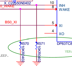
    Can you also show us how the WAKE lines are configured on the PHYs? You can draw a diagram, or if you want to send us the schematic, you can send me an E2E friend request to enable private messages.

    Best,

    Evan Su

  • Hi Evan,

    I already find out the root cause. There should be no network traffic in both PCBs when trying to enter TC-10. As a result, I need to disable and stop all network processes and network daemons before testing TC-10.

    Are both of these chips the DP83TC812?

    Yes.

    What is the value of the sleep fail interrupt flag (0x0018[13]) on the PHY that initiated the sleep negotiation?

    What register you need ? 0x0018, 0x0013 or 0x018D ?

    Did the other PHY (that did not initiate the sleep negotiation) raise an interrupt for Sleep Ack

    PHY INTn is not connected to MCU.

    WAKE ping configuration: (WAKE and INH connect to MCU with pull-down resistor)

    Can you tell me important registers for debugging TC-10 or chip state ?

    Thanks

  • Hi Mike,

    Glad to hear the issue was resolved.

    For future reference, the suggestions I mentioned before are useful for debugging TC-10 issues:

    What is the value of the sleep fail interrupt flag (0x0018[13]) on the PHY that initiated the sleep negotiation?

    This means bit 13 of register 0x0018. As described in the datasheet, this field indicates if there was a "Sleep Fail" event. A sleep fail event is triggered if either the link partner PHY did not transmit the sleep symbols back to the initiating PHY (which suggests there may be a problem with the other PHY), or if the MDI lines did not fall silent during the last monitoring period before entering a sleep state (which is what seems to have happened in your system).

    Did the other PHY (that did not initiate the sleep negotiation) raise an interrupt for Sleep Ack?

    Since the other PHY is not using the INT pin this probably isn't relevant in your case, but this is a method of checking if the link partner PHY successfully received the sleep symbols from the initiating PHY.

    Can you also show us how the WAKE lines are configured on the PHYs?

    This is more of a hardware configuration area, but we have seen instances of PHYs having sleep issues if there is unintentional electrical activity on the WAKE lines. The PHY could be accidentally woken up when it is sleeping. The external pulldown resistor in the datasheet is supposed to help reduce the chances of this happening and I see you have implemented it on your design.

    Best,

    Evan Su