This thread has been locked.

If you have a related question, please click the "Ask a related question" button in the top right corner. The newly created question will be automatically linked to this question.

TCA9555: Calculating Icc when driving LEDs

Part Number: TCA9555
Other Parts Discussed in Thread: TCA9535,

Tool/software:

Hi, I have a question regarding I/O Icc when using an I/O expander to drive an LED using either the TCA9555 or the TCA9535. Is there a way to calculate what the additional shoot-through current may be of an I/O input pin at a set value when the LED is in an off state?


Lets say in a situation where the I/O expander Vcc is at 5V, I/O pin is set to an input, and based on an LED forward voltage of ~0.9V(generated from leakage current) and a lower LED voltage rail of 3.3V, the input pin is held to about 2.4V.


  1. Does a higher Icc current even occur when using the TCA9555 because of the built in 100k pull up resistor on each I/O pin?

  2. For both parts (or just the TCA9535 given 1. if correct ) is there a way we can calculate what this additional shoot-through current is on the input stage from that lower input voltage? Could this additional current cause damage to the part?

  3. Does any of this apply when the pin is set to an output state and driven high?


Thankyou for your time.

  • 1. No.

    2. The shoot-through current is not specified.

    3. No. You should not configure a LED pin as an input.

  • Hi Kodi,

    Thank you for your questions. 

    Hi, I have a question regarding I/O Icc when using an I/O expander to drive an LED using either the TCA9555 or the TCA9535. Is there a way to calculate what the additional shoot-through current may be of an I/O input pin at a set value when the LED is in an off state?
    Lets say in a situation where the I/O expander Vcc is at 5V, I/O pin is set to an input, and based on an LED forward voltage of ~0.9V(generated from leakage current) and a lower LED voltage rail of 3.3V, the input pin is held to about 2.4V.

    From a datasheet perspective, there is no definite value for these conditions. I do know from lab testing a similar I/O expander across its input voltage that shoot-through current increased ICC by several mA for a single I/O. 

    Does a higher Icc current even occur when using the TCA9555 because of the built in 100k pull up resistor on each I/O pin?

    Depending on if you are driving HIGH or LOW externally on the I/O pins configured as inputs. It makes sense you would burn more current in the TCA9555 when pulling LOW because there will be current flow from VCC --> 100k --> GND. 

    For both parts (or just the TCA9535 given 1. if correct ) is there a way we can calculate what this additional shoot-through current is on the input stage from that lower input voltage? Could this additional current cause damage to the part?

    It is not listed out in the datasheet or validated. However, in my previous reply, my lab bench testing showed several mA when floating the voltage mid-rail on the INPUT. 

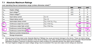
    No damage to the part since the abs. max input voltage and currents are respected. 

    Does any of this apply when the pin is set to an output state and driven high?

    You avoid shoot-through current since the pin is not allowed to float. The output will be either HIGH or LOW with VOH / VOL respectively. 

    Regards,

    Tyler

  • Thankyou both for the replies!

    I should have been more specific.

    From what I understand, both of these parts in a POR state configure all of the I/O pins as inputs. In my application I have an indeterminate amount of time (potentially a long duration of time) between power on and when the controller will configure the I/O pins, so I need to pay attention to what these parts are doing if all I/O are set to an input state, even if the pins are meant to be outputs, driving LEDs. 

    Excess current consumption will not be an issue for me in this state, provided I don't exceed the limits of the part. It may be beneficial for me to run a test similar to what you've described, do you recall if your bench testing yielded less than 10mA with 1 of those I/O floating at mid-rail?

    Thanks again!

    -Kodi