Other Parts Discussed in Thread: TCA9548A
Tool/software:
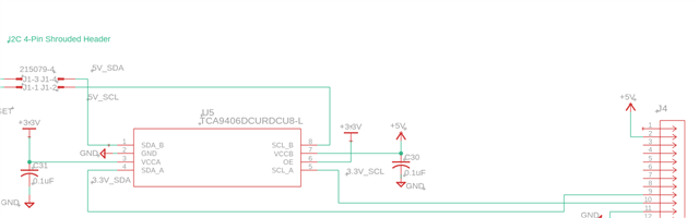
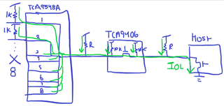
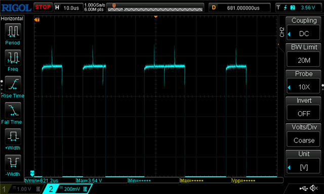
We are using the TCA9406 to translate from 3.3V to 5V, and are seeing seemingly random failures where either the SDA or SCL lines (on either the A or B side) measure out a low resistance (50 to 140 Ohm) with respect to ground. This makes any attached devices lose control of the bus, since the signals are held to a low voltage of ~0.8V.
The master side is an offboard FPGA connected to another TCA9406 for 1.8V to 3.3V translation, and the 5V side is an offboard microcontroller. We are utilizing the internal pullups on the 2 chained TCA ICs on the 3.3V side, and the 5V side has internal pullups on the MCU of ~20kOhm.
These devices are not being hot-plugged, but they do get power cycled arbitrarily. They generally work well, functioning during initial bootup and installation, but seemingly spontaneously fail, possibly after being power cycled, or possibly mid-operation. It should be noted that we have tied the OE to VCCA, so the device is not being disabled during power cycling.
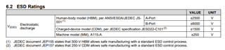
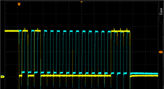
Obviously there is some damage to the device, but it is not clear how such a thing would happen. The power supplies are generally fairly well regulated, and it seems strange that the device would fail spontaneously. My best guess is somehow some ESD damage that weakened the device, coupled with some transient surge that finally did it in? I have captured the boot-up and down sequences, though, and they are nice and clean ~2ms ramp ups.
We are considering just changing parts and communication scheme (UART), but any guidance on possible short-term suggestions for alleviating these failures would be greatly appreciated.