Other Parts Discussed in Thread: SK-AM62B-P1, DP83869HM
Tool/software:
Hi,
I have two DP83869EVm boards, and have tied up both RGMIIs back to back with a short jumper.
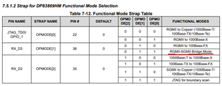
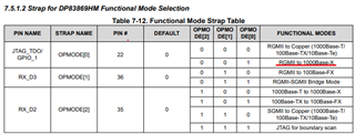
On EVM1 (Fiber-RGMII), OP_MD[2:0] = 001 for 1000Mbps base mode (tried auto and forced negotiation), and on EVM2 (RGMII-Cu) OP_MD[2:0] = 000.
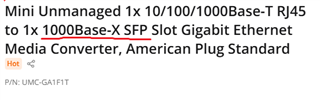
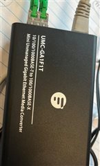
PC<---> UMC-GA1F1T(Electrical to Fiber - 1000base) <---> EVM1(Fiber-RGMII) <---> EVM2 (RGMII-Copper) <---> Host(SK-AM62b-P1 TI board can be ping - 192.168.100.1)
When both boards turned on:
EVM1:
- LED0 is in forced fiber mode (high), and LED1&2 are low
- LED0 lights up.
- LED 1 blinks synchronously with EVM2-LED2 and the host RJ45 LED, and 3 of them blink at the same time.
- LED 2 is off
EVM2:
LED0,1&2 - pin 47, 46,45 are low (grounded)
- LED0 lights up.
- LED1 is on
- LED2 blinks synchronously with EVM1-LED1 and the host RJ45 LED.
I tried pinging the board, but it's failing. Can someone help me with this?
for EVM2, i tried to change the reg as well but no luck
7.4.8.1 RGMII-to-Copper Ethernet Mode Required register configuration when switching to RGMII-to-Copper mode using software:
• Write 0x0040 to register 1DFh // Set Operation Mode to RGMII to Copper
• Write 0x1140 to register 0h // Reset BMCR
• Write 0x01E1 to register 4h // Advertise 100Base-TX and 10Base-T ability
• Write 0x0300 to register 9h // Reset GEN_CFG1 • Write 0x5048 to register 10h // Reset PHY_CONTROL
• Write 0x4000 to register 1Fh // Software Reset