This thread has been locked.

If you have a related question, please click the "Ask a related question" button in the top right corner. The newly created question will be automatically linked to this question.

SN65DSI86: TI SN65DSI86 to eDP Panel (NT156FHM-N41) - No AUX Communication with raspberrypi compute module 4(6.6.y linux kernel)

Part Number: SN65DSI86

Tool/software:

Hi everyone,

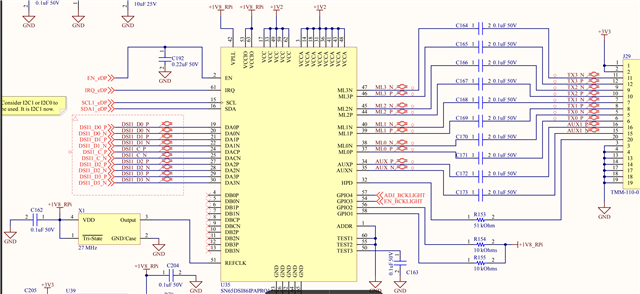
I'm working on interfacing a TI SN65DSI86 DSI-to-eDP bridge chip with a Raspberry Pi Compute Module 4 and an NT156FHM-N41 eDP panel.

I've successfully verified the data path by displaying a test bar pattern on the panel, so the basic connectivity seems okay. However, I'm running into an issue with the AUX channel communication between the bridge chip and the panel.

Here's the situation:

  • The eDP protocol uses AUX lines (AUX_P/N) for control communication, including EDID and DPCD retrieval.
  • The Linux kernel driver on the Raspberry Pi attempts to use this AUX channel to get the EDID information for display initialization. This is currently failing, and the display pipeline isn't being set up.
  • I've written simple scripts to directly communicate with the panel via the bridge to read EDID and DPCD, but these are also failing to receive any data. This strongly suggests a problem with the AUX communication itself.
  • I've already tried swapping the AUX_P and AUX_N wires with no change.

The panel I'm using is the NT156FHM-N41 (datasheet: BOE NT156FHM-N41). I'm looking for suggestions on what to investigate next to get the AUX communication working.

Could there be specific hardware considerations (like termination, pull-ups, signal integrity) I should be looking at? Are there any specific configuration settings on the SN65DSI86 that are crucial for AUX communication? Any insights or experiences with similar setups would be greatly appreciated!

Thanks in advance for your help!

SN65DSI86_interfacing

  • Hello Bhavin,

    Have you probed and observed activity on the AUX channel whenever the transactions are initiated? Please check the waveforms to confirm there is activity over the aux channel.

    Please check the datasheet direct and indirect methods for I2C over aux: "8.4.5.3 I2C-Over-AUX" section. Which method are you using? Could you share the script for how you are initiating these steps. 

    What mode of DP link training is used for your system? Is the AUX used for link training in the mode you have set up?

    Best regards,
    Ikram

  • Not yet, we wanted to confirm our software configuration first. We'll do the probing.

    Yes, we are following indirect methods in our test scripts. I am adding the scripts below

    We used semi-auto link training for test patterns as suggested in the SN65DSI86 programming guide by TI.
    Our Aim is to interface the mentioned edp panel to Raspberry Pi over the DSI port by using this bridge chip. From the Linux kernel driver, we would like to utilise the existing sn65dsi86.c(https://github.com/raspberrypi/linux/blob/rpi-6.6.y/drivers/gpu/drm/bridge/ti-sn65dsi86.c) driver and panel-edp.c(https://github.com/raspberrypi/linux/blob/rpi-6.6.y/drivers/gpu/drm/panel/panel-edp.c) driver. While configuring those drivers, we are seeing the panel driver is failing to read EDID and to confirm that, we tried with the test scripts, which gave the same results, EDID read as all zeros.
    Our understanding is that this driver should work out of the box with the correct configuration made as suggested in the device trees Documentation(https://github.com/raspberrypi/linux/blob/rpi-6.6.y/Documentation/devicetree/bindings/display/bridge/ti%2Csn65dsi86.yaml).

    EDID_read2.sh
     

    #!/bin/bash
    
    I2C_DEV=1
    BRIDGE_ADDR=0x2c
    
    # 1. Enable EDID I2C address claim (0x50 with enable bit)
    i2cset -y -f $I2C_DEV $BRIDGE_ADDR 0x60 0x61 #0xA1  # 0xA1 = 0b10100001
    
    # 2. Set AUX_ADDR for I2C-over-AUX EDID address (high/mid = 0)
    i2cset -y -f $I2C_DEV $BRIDGE_ADDR 0x74 0x00  # AUX_ADDR[19:16]
    i2cset -y -f $I2C_DEV $BRIDGE_ADDR 0x75 0x00  # AUX_ADDR[15:8]
    i2cset -y -f $I2C_DEV $BRIDGE_ADDR 0x76 0x30 #0x50  # AUX_ADDR[7:0] — EDID address
    
    # 3. Set length to 16 bytes (0x10) — can read full EDID by looping
    i2cset -y -f $I2C_DEV $BRIDGE_ADDR 0x77 0x10
    
    # 4. Set command to I2C read (0x09 = I2C-over-AUX Read Request)
    #     Format: (CMD << 4) | 0x01 = 0x91
    i2cset -y -f $I2C_DEV $BRIDGE_ADDR 0x78 0x91
    
    # 5. Poll until SEND bit (bit 0 of 0x78) is cleared (max timeout 1s)
    timeout_ms=1000
    elapsed=0
    while true; do
        val=$(i2cget -y -f $I2C_DEV $BRIDGE_ADDR 0x78)
        if (( (val & 0x01) == 0 )); then
            break
        fi
        sleep 0.01
        elapsed=$((elapsed + 10))
        if (( elapsed >= timeout_ms )); then
            echo "ERROR: AUX transaction timed out"
            exit 1
        fi
    done
    
    # 6. Read back data (AUX_RDATA0 - AUX_RDATA15)
    echo "EDID chunk (16 bytes):"
    for i in $(seq 0 15); do
        reg=$((0x79 + i))
        byte=$(i2cget -y -f $I2C_DEV $BRIDGE_ADDR $reg)
        printf "%s " "$byte"
    done
    echo


    EDID_read.sh
    #!/bin/bash
    
    I2C_DEV=1        # Replace with correct I2C bus
    BRIDGE_ADDR=0x2c           # SN65DSI86 I2C address
    EDID_ADDR=0x50             # Standard EDID I2C address
    NUM_BLOCKS=1               # EDID block count (1 = 128 bytes)
    BYTES_PER_BLOCK=128
    
    # Enable I2C Claim1 for EDID address (0x50)
    i2cset -y -f $I2C_DEV $BRIDGE_ADDR 0x60 $((EDID_ADDR << 1 | 1)) # 7:1 address + EN bit
    
    # Function to read EDID block (16 bytes at a time)
    read_block() {
        local offset=$1
        for ((i=0; i<BYTES_PER_BLOCK; i+=16)); do
            # Set AUX_ADDR[7:0] to EDID address (0x50)
            i2cset -y -f $I2C_DEV $BRIDGE_ADDR 0x77 $EDID_ADDR
    
            # Set AUX_LENGTH (0x74) to 16
            i2cset -y -f $I2C_DEV $BRIDGE_ADDR 0x74 0x10
    
            # Set AUX_CMD (0x78) to 0x9 (I2C Read)
            # Set SEND bit (bit 0) to trigger transaction
            i2cset -y -f $I2C_DEV $BRIDGE_ADDR 0x78 0x91
    
            # Poll until SEND bit clears
            while true; do
                val=$(i2cget -y -f $I2C_DEV $BRIDGE_ADDR 0x78)
                if (( val & 0x01 == 0 )); then
                    break
                fi
                printf "Poll until SEND  bit clears"
                sleep 0.01
            done
    
            # Read 16 bytes from AUX_RDATA0–15 (0x79 to 0x88)
            printf "EDID offset 0x%02X: " $((offset + i))
            for ((j=0; j<16; j++)); do
                byte=$(i2cget -y -f $I2C_DEV $BRIDGE_ADDR $((0x79 + j)))
                printf "%s " "$byte"
            done
            echo
        done
    }
    
    # Read full EDID
    for ((block=0; block<NUM_BLOCKS; block++)); do
        read_block $((block * BYTES_PER_BLOCK))
    done


    DPCD_read.sh
    #!/bin/bash
    
    I2C_DEV=1               # Replace with correct I2C bus (e.g., /dev/i2c-2)
    BRIDGE_ADDR=0x2c        # SN65DSI86 I2C address
    DPCD_ADDR=(0x00 0x00 0x00)  # DPCD base address is 0x00000
    
    # Write DPCD address to AUX_ADDR registers (0x74, 0x75, 0x76)
    i2cset -y -f $I2C_DEV $BRIDGE_ADDR 0x74 ${DPCD_ADDR[0]} b
    i2cset -y -f $I2C_DEV $BRIDGE_ADDR 0x75 ${DPCD_ADDR[1]} b
    i2cset -y -f $I2C_DEV $BRIDGE_ADDR 0x76 ${DPCD_ADDR[2]} b
    
    # Set AUX length to 16 bytes
    i2cset -y -f $I2C_DEV $BRIDGE_ADDR 0x77 0x10 b
    
    # Set AUX_CMD to 0x2 (AUX read)
    # Set SEND = 1 to initiate transaction
    i2cset -y -f $I2C_DEV $BRIDGE_ADDR 0x78 0x21 b
    
    # Poll until SEND bit clears
    for i in {1..100}; do
        val=$(i2cget -y -f $I2C_DEV $BRIDGE_ADDR 0x78)
        if (( (val & 0x01) == 0 )); then
            break
        fi
        sleep 0.01
    done
    
    # Check if it timed out
    if (( (val & 0x01) != 0 )); then
        echo "Timeout waiting for AUX transaction to complete."
        exit 1
    fi
    
    # Read back 16 bytes from AUX_RDATA0–AUX_RDATA15 (0x79–0x88)
    echo "DPCD Response:"
    for ((i=0; i<16; i++)); do
        reg=$((0x79 + i))
        data=$(i2cget -y -f $I2C_DEV $BRIDGE_ADDR $reg)
        printf "0x%02x " $data
    done
    echo


    prog_guild_pattr.sh
    #!/bin/bash
    
    I2CBUS=1        # Adjust as per your I2C bus
    ADDR=0x2c       # SN65DSI86 I2C address
    
    if [ $# -gt 0 ]; then
    	ASSR=1
    else
    	ASSR=0
    fi
    
    echo "ASSR:$ASSR"
    
    raspi-gpio set 20 op dl
    sleep 1
    raspi-gpio set 20 op dh
    
    # Helper to write a register
    w() {
      i2cset -y $I2CBUS $ADDR $1 $2
    }
    
    echo "[INFO] Configuring SN65DSI86 for test pattern..."
    if [ "$ASSR" -eq 0 ]; then
    	echo "configuring Non ASSR"
    	w 0xff 0x07
    	w 0x16 0x01
    	w 0xff 0x00    
    fi
    
    # Configure REFCLK 27 MHz
    w 0x0a 0x06
    
    # DSI A 4 Lanes
    w 0x10 0x20
    
    #DSIA Freq 445MHz
    w 0x12 0x59
    
    if [ "$ASSR" -eq 1 ]; then
    	w 0x5a 0x05
    else
    	#Enhance framing NO ASSR
    	w 0x5a 0x04
    fi
    
    #DP link rate 2.7 Gbps
    w 0x94 0x80
    
    # DP Lanes 2, no SSC
    w 0x93 0x20
    
    # Enable PLL
    w 0x0d 0x01
    sleep 0.1
    
    if [ "$ASSR" -eq 1 ]; then
    	echo "configuring ASSR"
    	w 0x95 0x00
    	w 0x64 0x01
    	w 0x74 0x00
    	w 0x75 0x01
    	w 0x76 0x0a
    	w 0x77 0x01
    	w 0x78 0x81
    	sleep 0.10
    fi
    
    # Semi auto train
    w 0x96 0x0a
    sleep 0.2
    
    # Video Parameters
    # Horizontal active: 1920
    w 0x21 $(( (1920 >> 8) & 0xFF ))
    w 0x20 $(( 1920 & 0xFF ))
    
    # Vertical active: 1080
    w 0x25 $(( (1080 >> 8) & 0xFF ))
    w 0x24 $(( 1080 & 0xFF ))
    
    # Horizontal front porch and back porch
    w 0x38 207
    w 0x34 48
    
    # HSync width: 32
    w 0x2c 32
    
    # vertical front porch and back porch
    w 0x3a 71
    w 0x36 3
    
    # VSync width: 6
    w 0x30 6
    
    # Dp 24 bpp
    w 0x5b 0x00
    
    # Color Bar enable
    w 0x3c 0x14 #12 = 3 color working
    
    # enhanced framing, ASSR, and Vstream enable
    w 0x5a 0x0d
    
    echo "[DONE] Test pattern should now be visible on the panel."


  • Hi Bhavin,

    1. I am not familiar with the driver code that you shared. Could you tell us where you got this?

    The software that we have for this device are:

    DSI Driver code: https://github.com/torvalds/linux/blob/master/drivers/gpu/drm/bridge/ti-sn65dsi86.c

    DSI register calculator: https://e2e.ti.com/support/interface-group/interface/f/interface-forum/945404/faq-sn65dsi86-how-do-i-programming-the-sn65dsi86-registers?tisearch=e2e-sitesearch&keymatch=sn65dsi86#

    Y
    ou can use the calculator tool above as well to input your configurations and generate a script for I2C for initialization.

    2. For the I2C over aux steps, please give me 1-2 days to check the "EDID_read" scripts you shared and to match it with the datasheet.

    Let me know whether you are able to probe and check for AUX channel activity. Also, you are using the TI EVM to test the DSI86 part right?


    Best regards,
    Ikram

  • Please find my inline replies below,
    1. I am not familiar with the driver code that you shared. Could you tell us where you got this?
    It is the same driver you pointed out. The driver reference you shared is from the mainline kernel, and the one we use is the official version of Raspberry Pi created from the Linux kernel for Raspberry Pi use cases.
     
    2. For the I2C over aux steps, please give me 1-2 days to check the "EDID_read" scripts you shared and to match it with the datasheet.
    Yes please, have a look and let us know. Please note EDID_read.sh and EDID_read2.sh are somewhat similar; the only difference is in EDID_read2.sh we are only reading the first 16 bytes.
     
    Also, you are using the TI EVM to test the DSI86 part right?
    No, we have our custom PCB having this bridge chip interfaced with Raspberry Pi CM4 DSI1 port.
  • Hi Bhavin, I will check the script and get back to you.

    Thank you,
    Ikram

  • Hi Bhavin,

    I am sorry for the delay on this. From the "EDID_read2.sh" script, it seems you are setting the AUX_ADDR to 0x30, not 0x50. Is this correct for your application?

    Also, you are setting 0x78 to 0x91, instead of 0x41. Can you use the AUX_CMD  = 0x4 for "I2C-Over-Aux Write MOT = 1" option instead?

    This previous E2E has a small portion of the code at the end: https://e2e.ti.com/support/interface-group/interface/f/interface-forum/957141/sn65dsi86-q1-i2c-detection-problem

    Also, if your system allowed clock stretching, then you can consider using the Direct method to simplify the sequence.

    Best regards,
    Ikram

  • From the "EDID_read2.sh" script, it seems you are setting the AUX_ADDR to 0x30, not 0x50. Is this correct for your application?
    It does not work with 0x50 as well. We were trying an alternative address 0x30, as we found somewhere on the internet, just as part of debugging. You can notice that 0x50 part is commented out in the same line.
     
    Also, you are setting 0x78 to 0x91, instead of 0x41. Can you use the AUX_CMD  = 0x4 for "I2C-Over-Aux Write MOT = 1" option instead?
    Sure, will give a try.
     
    Also, if your system allowed clock stretching, then you can consider using the Direct method to simplify the sequence.
    Can you help us with the command sequence for the Direct method of communication?
  • Hi Bhavin,

    Here's a previous E2E thread about the direct method: https://e2e.ti.com/support/interface-group/interface/f/interface-forum/949449/sn65dsi86-i2c-over-aux-direct-method/3508159

    The script syntax is from the Aardvark I2C adapter

    Thank you,
    Ikram