This thread has been locked.

If you have a related question, please click the "Ask a related question" button in the top right corner. The newly created question will be automatically linked to this question.

SN65DSI86-Q1: I2C detection problem

Part Number: SN65DSI86-Q1
Other Parts Discussed in Thread: SN65DSI86, TEST2

Hi,

We are working with SN65DSI86 module on a custom IMX8MM board, we checked that the module is powered and enabled correctly.

The module is conencted to the I2C_1 bus.

When booting the Kernel, we check the presence of the module with "i2cdetect -a 0" but there is no module on 0x2d.

We tried to activate the SN65DSI86 driver in the Kernel 5.4.27 and patched the Kernel and Uboot DTS files like this:

sn65_bridge: sn65dsi86@2c {
		#address-cells = <1>;
		#size-cells = <0>;
		compatible = "ti,sn65dsi86";
		reg = <0x2c>;
		ti,dsi-lanes = <4>;
		max,dsi-channel = <1>;
		ti,dp-lanes = <2>;
		status = "okay";
		enable-gpios = <&gpio1 9 GPIO_ACTIVE_HIGH>;
		interrupts-extended = <&gpio1 10 IRQ_TYPE_EDGE_FALLING>;
		vccio-supply = <&ldo6_reg>;	//1.8V
		vcca-supply = <&buck1_reg>;	//1.2V
		vpll-supply = <&ldo6_reg>;	//1.8V
		vcc-supply = <&buck1_reg>;	//1.2V
		clock-names = "refclk";
		clocks = <&clk IMX8MM_CLK_DSI_CORE>,
			     <&clk IMX8MM_CLK_DSI_PHY_REF>;
		panel@0 {
			reg = <0>;
			pinctrl-0 = <&pinctrl_mipi_dsi_en>;
			enable-gpio = <&gpio1 9 GPIO_ACTIVE_HIGH>;
			panel-width-mm = <68>;
			panel-height-mm = <130>;
			port {
				panel1_in: endpoint {
					remote-endpoint = <&sn65_out>;
				};
			};
		};
		ports {
			#address-cells = <1>;
			#size-cells = <0>;
			port@0 {
				reg = <0>;
				sn65_in: endpoint {
					remote-endpoint = <&dsim_to_sn65>;
				};
			};
			port@1 {
				reg = <1>;
				sn65_out: endpoint {
					data-lanes = <0 1 2 3>;
					lane-polarities = <0 1 0 1>;
					remote-endpoint = <&panel1_in>;
				};
			};
		};
		
	};
&mipi_dsi {
	status = "okay";

	port@1 {
		dsim_to_sn65: endpoint {
			remote-endpoint = <&sn65_in>;
			attach-bridge;
		};
	};
};

We didn't do anything with Uboot to add the video variable to bootargs for the moment.

After these modifications this error shows:

# dmesg | grep drm
[    0.894170] imx-drm soc@0:bus@32c00000:display-subsystem: no available port
[    4.229399] [drm:ti_sn_bridge_probe [ti_sn65dsi86]] *ERROR* could not find any panel node
[    4.270746] [drm:ti_sn_bridge_probe [ti_sn65dsi86]] *ERROR* could not find any panel node
[    4.353747] [drm:ti_sn_bridge_probe [ti_sn65dsi86]] *ERROR* could not find any panel node
[    4.432826] [drm:ti_sn_bridge_probe [ti_sn65dsi86]] *ERROR* could not find any panel node
[    4.673391] [drm:ti_sn_bridge_probe [ti_sn65dsi86]] *ERROR* could not find any panel node
[    4.682721] [drm:ti_sn_bridge_probe [ti_sn65dsi86]] *ERROR* could not find any panel node
  • Is there a problem with the module that it can't be shown in i2cdetect?
  • Is the DTS file correct?
  • Do we need to port Uboot to VIDEO support for it?

Thanks, Talel

  • Talel

    Do you have a standalone I2C controller that you can use to verify the DSI86 I2C interface is working properly?

    Thanks

    David

  • Hi David,

    Actually we don't have a standalone I2C controller, we tried to integrate an external I2C flash memory on the same I2C1 bus and it appears in i2cdetect, but the SN65 still unseen.

    Can the hardware implementation (schematics) ,of our DSI module, help you?

    Thanks, Talel

  • Talel

    I am trying to differentiate the issue between the HW and the SW.

    Do you have multiple device on the same I2C bus or just DSI86 itself? If there are multiple devices on the I2C bus, is it possible to isolate the DSI86 by itself?

    In terms of the hardware implementation, I would recommend

    • A 0.22uF cap on the EN pin to make sure the DSI86 has the proper power sequence
    • 2k or 4.7k on SCL/SDA being pulled up to 1.8V

    Do you have a way to probe the I2C bus to verify there is actual I2C traffic?

    Thanks

    David

  • Hi David,

    The SDI86 is on I2C1 with the PMIC getting 1.8V, we cannot isolate the DSI86 alone on I2C1.

    The PMIC is already on address 0x4b and it show up with i2cdetect.

    ---

    • A 0.22uF cap on the EN pin to make sure the DSI86 has the proper power sequence
    • 2k or 4.7k on SCL/SDA being pulled up to 1.8V

    Yes this is exactly what we have in our schematic.

    • Do you have a way to probe the I2C bus to verify there is actual I2C traffic?

    Yes we verified the actual I2C traffic and it is okay.

    Thanks, Talel

  • Talel

    Can you modify the code and read only the DSI86 registers from 0x00 to 0x08? These are read-only registers that will return the DSI86 Device ID and Revision ID. You should be able to decode the I2C traffic on the scope.

    For the read operation,

    1. The master initiates a read operation by generating a start condition (S), followed by the SN65DSI86 7-bit address and a one-value W/R bit to indicate a read cycle.

    2. The SN65DSI86 acknowledges the address cycle.

    3. The SN65DSI86 transmit the contents of the memory registers MSB-first starting at register 00h or last read subaddress+1. If a write to the SN65DSI86 I2C register occurred prior to the read, then the SN65DSI86 will start at the subaddress specified in the write.

    4. The SN65DSI86 will wait for either an acknowledge (ACK) or a not-acknowledge (NACK) from the master after each byte transfer; the I2C master acknowledges reception of each data byte transfer.

    5. If an ACK is received, the SN65DSI86 transmits the next byte of data.

    6. The master terminates the read operation by generating a stop condition (P).

    Thanks

    David

  • Hi David,

    After lot of investigation we found out a problem in our PCB, so we fixed it and now the bridge is appearing on 0x2d with i2cdetect:

    ~# i2cdetect -y 0
         0  1  2  3  4  5  6  7  8  9  a  b  c  d  e  f
    00:          -- -- -- -- -- -- -- -- -- -- -- -- -- 
    10: -- -- -- -- -- -- -- -- -- -- -- -- -- -- -- -- 
    20: -- -- -- -- -- -- -- -- -- -- -- -- -- 2d -- -- 
    30: -- -- -- -- -- -- -- -- -- -- -- -- -- -- -- -- 
    40: -- -- -- -- -- -- -- -- -- -- -- UU -- -- -- -- 
    50: -- -- -- -- -- -- -- -- -- -- -- -- -- -- -- -- 
    60: -- -- -- -- -- -- -- -- -- -- -- -- -- -- -- -- 
    70: -- -- -- -- -- -- -- --

    I read data from 0x00 to 0x08 correctly.

    Now when using the same device tree file mentioned in top of the post, same error appears:

    [    4.631620] [drm:ti_sn_bridge_probe [ti_sn65dsi86]] *ERROR* could not find any panel node

    Thanks, Talel

  • Hi David,

    We are using a DSI to eDP bridge.

    I have a question may help me understand the work I need to do:

    • Do I need to add sn65dsi86,addresses block with its values ? If yes from where I can get them, from datasheet ?
    • Do I need to configure the panel@0 compatible with the panel I want to attach ? with its timings ?

    Thanks,

    Talel

  • Talel

    Can you please clarify the first question? 

    You need to configure the DSI86 with the proper panel timing using the panel EDID info, attached is a link to a spreadsheet you can use to generate the DSI86 registers programming value based on the panel EDID information.

    Can you also use to see if you can correctly read the panel EDID info? 

    Read Sink’s EDID (Direct Method)
    This script will read 256 bytes of the EDID.
    <aardvark>
    <configure i2c="1" spi="1" gpio="0" tpower="1" pullups="0" />
    <i2c_bitrate khz="100" />
    ======Enable I2C_ADDR_CLAIM1======
    <i2c_write addr="0x2D" count="1" radix="16">60 A1</i2c_write> />
    ======Write EDID base of 00 ======
    <i2c_write addr="0x50" count="0" radix="16">00</i2c_write> />
    ======Read 256 bytes of EEID======
    <i2c_read addr="0x50" count="256" radix="16">00</i2c_read> />
    </aardvark>

    Thanks
    David

  • Hi David,

    Thanks for the reply.

    For the first question I meant something like this in the device tree, I saw this on someone's DTS:

    sn65dsi86,addresses = <0x0A 0x10 0x12 0x5A 
                                           0x93 0x94 0x0D 0x95 
                                           0x64 0x74 0x75 0x76 
                                           0x77 0x78 0x96 0x20 
                                           0x21 0x24 0x25 0x2C 
                                           0x2D 0x30 0x31 0x34 
                                           0x36 0x38 0x3A 0x5B 
                                           0x3C 0x5A>;
    
            sn65dsi86,values = <0x06 0x26 0x59 0x05  
                                        0x20 0x80 0x01 0x00
                                        0x01 0x00 0x01 0x0A
                                        0x01 0x81 0x0A 0x80
                                        0x07 0x38 0x04 0x2C
                                        0x00 0x05 0x80 0x94
                                        0x24 0x58 0x04 0x00
                                        0x00 0x0D>;
    

    Actually this is my first time working on DSI and SN65DSI86, I will try to understand and use the spreadsheet, and I will post any updates.

    Thanks for the great support.

    Talel

  • Talel

    When you use the spreadsheet to generate the DSI86 register programming value, you would see something like this as an example.

    <aardvark>
    <configure i2c=1 spi=1 gpio=0 tpower=1 pullups=0/>
    <i2c_bitrate khz=100/>

    ======ASSR RW control ======
    <i2c_write addr=0x2D count=1 radix=16> FF 7 </i2c_write>/>
    <i2c_write addr=0x2D count=1 radix=16> 16 1 </i2c_write>/>
    <i2c_write addr=0x2D count=1 radix=16> FF 0 </i2c_write>/>

    ======REFCLK Frequency ======
    <i2c_write addr=0x2D count=1 radix=16> 0A 6 </i2c_write>/>

    ======DSI Mode ======
    <i2c_write addr=0x2D count=1 radix=16> 10 26 </i2c_write>/>

    ======DSIA Clock ======
    <i2c_write addr=0x2D count=1 radix=16> 12 5C </i2c_write>/>

    ======DSIB Clock ======
    <i2c_write addr=0x2D count=1 radix=16> 13 5C </i2c_write>/>

    ======DP Datarate ======
    <i2c_write addr=0x2D count=1 radix=16> 94 80 </i2c_write>/>

    ======Enable PLL ======
    <i2c_write addr=0x2D count=1 radix=16> 0D 1 </i2c_write> <sleep ms=10/>

    ======Enable enhanced frame in DSI86 ======
    <i2c_write addr=0x2D count=1 radix=16> 5A 4 </i2c_write>/>

    ======Number of DP lanes ======
    <i2c_write addr=0x2D count=1 radix=16> 93 20 </i2c_write>/>

    ======Start Semi-Auto Link Training ======
    <i2c_write addr=0x2D count=1 radix=16> 96 0A </i2c_write> <sleep ms=20/>

    ======CHA Active Line Length ======
    <i2c_write addr=0x2D count=2 radix=16> 20 70 08 </i2c_write>/>

    ======CHB Active Line Length ======
    <i2c_write addr=0x2D count=2 radix=16> 22 0 0 </i2c_write>/>

    ======Vertical Active Size ======
    <i2c_write addr=0x2D count=2 radix=16> 24 A0 05 </i2c_write>/>

    ======Horizontal Pulse Width ======
    <i2c_write addr=0x2D count=2 radix=16> 2C 20 00 </i2c_write>/>

    ======Vertical Pulse Width ======
    <i2c_write addr=0x2D count=2 radix=16> 30 0A 00 </i2c_write>/>

    ======HBP ======
    <i2c_write addr=0x2D count=1 radix=16> 34 50 </i2c_write>/>

    ======VBP ======
    <i2c_write addr=0x2D count=1 radix=16> 36 1B </i2c_write>/>

    ===== HFP ======
    <i2c_write addr=0x2D count=1 radix=16> 38 30 </i2c_write>/>

    ===== VFP ======
    <i2c_write addr=0x2D count=1 radix=16> 3A 03 </i2c_write>/>

    ===== DP-18BPP Disable ======
    <i2c_write addr=0x2D count=1 radix=16> 5B 0 </i2c_write>/>

    ===== Color Bar Enable ======
    <i2c_write addr=0x2D count=1 radix=16> 3C 12 </i2c_write>/>

    ===== Enhanced Frame, and Vstream Enable ======
    <i2c_write addr=0x2D count=1 radix=16> 5A 0C </i2c_write>/>

    </aardvark>

    0x2D is the DSI86 I2C access. 0x0A, 0x10, 0x12, 0x3C, 0x5A is the DSI86 individual register address which goes into sn65dsi86,addresses. Next to 0x0A, 0x10, 0x12, 0x3C, 0x5A is 0x06, 0x26, 0x5C, 0x12, 0x0C, these are the values being programmed into each register and correspond to sn65dsi86,values.

    Thanks

    David

  • Hi David,

    While I'm looking into the spreadsheet, I want to ask a question about what we are doing

    As far as I understand the Spreadsheet, I need to input Panel information which is eDP panel, so I need to specify the information of a particular Panel?

    Besides, we need to work with HDMI via an eDP to HDMI adapter to work with all type of monitors, is that possible?

    Thanks for the great support.

    Talel

  • Talel

    As far as I understand the Spreadsheet, I need to input Panel information which is eDP panel, so I need to specify the information of a particular Panel?

    This is correct, the DSI86 needs to be programmed with the specific panel timing info.

    If you need to work with multiple monitors, then you would need to read the monitors' EDID first over AUX. Once you read the EDID, then you need to update the DSI86 registers with the new monitor timing info.

    Thanks

    David

  • Hi David,

    Thanks again for the great support and help.

    I will put a summary for all work need to be done in order to make SN65DSI86 work properly as we need, and it is actually to clear the air about the DSI work, because it is the first time for us:

    • Get an USB to I²C module like Aardvark as recommended in the Spreadsheet
      • Can we develop a program with Linux I²C (linux/i2c.h) library to run scripts like aardvark's following the datasheet's read/write parts?

    • If one specific panel is needed, then one should get its EDID info (from panel datasheet or from custom Aardvark script) and set it in the spreadsheet to get a script that programs the DSI86 register.
    • If multiple monitors needed, then the ti-sn65dsi86.cdriver need to be patched to read EDID on hotplug and set the DSI86 registers directly (This is from where we got the idea of developing a custom I²C program with Linux I²C library alernatively to Aardvark or any USB to I²C module)
      • Is TEST2 pin need to be high to do this?
    • Configure the kernel Device Tree Source to define the I²C subnode and the mipi_dsi node with proper "sn65dsi86,addresses" and "sn65dsi86,values"
    • Set a video parameter to bootloader bootargs in order to detect the mipi_dsi, like: video=mxcfb0:dev=mipi_dsi,TRULY-WVGA,if=RGB24

    Thanks,

    Talel

  • Talel

    • Get an USB to I²C module like Aardvark as recommended in the Spreadsheet
      • Can we develop a program with Linux I²C (linux/i2c.h) library to run scripts like aardvark's following the datasheet's read/write parts?
        • Aardvark is what we used in the lab to read/write the DSI86 registers, I don't see an issue with using the Linux I2C library to read/write the DSI86. You can read the DSI86 registers from 0x00 to 0x08 to verify the library function is working properly.   
    • If one specific panel is needed, then one should get its EDID info (from panel datasheet or from custom Aardvark script) and set it in the spreadsheet to get a script that programs the DSI86 register.
      • Correct. The EDID provides the panel supported resolution, you also need to know the number of eDP lane and data rate being supported by the panel. 
    • If multiple monitors needed, then the ti-sn65dsi86.cdriver need to be patched to read EDID on hotplug and set the DSI86 registers directly (This is from where we got the idea of developing a custom I²C program with Linux I²C library alernatively to Aardvark or any USB to I²C module)
      • Is TEST2 pin need to be high to do this?
        • I would recommend keeping TEST2 pin high to disable the DSI86 ASSR since external monitors do not support ASSR per the DP spec.
    • Configure the kernel Device Tree Source to define the I²C subnode and the mipi_dsi node with proper "sn65dsi86,addresses" and "sn65dsi86,values"
      • Correct, besides the monitor EDID which provides the monitor supported resolution, you also need to read the monitor's DPCD registers to know the monitor supported DP lane and data rate before you start the DP link training. 
    • Set a video parameter to bootloader bootargs in order to detect the mipi_dsi, like: video=mxcfb0:dev=mipi_dsi,TRULY-WVGA,if=RGB24
    • Correct

    Thanks

    David

  • Hi David,

    Thanks for the help and for the confirmation.

    For the moment we don't have an USB to I²C adapter like Aardvark, so we will try to develop a software that program the registers directly from the CPU I²C master under Linux.

    We will try to work the Aardvark's output script as an input for our software. Any suggestions?

    Now we have a nother problem with is the driver is not detecting the SN65DSI86 and same error occurs:

    [drm:ti_sn_bridge_probe [ti_sn65dsi86]] *ERROR* could not find any panel node

    I'm using the same DTS source as posted first in this post.

    I will try to remove the DTS definition and patch the driver with the detect function directly passing the SN65DSI86 0x2d address and try it.

    Thanks,

    Talel

  • Hi David,

    I've tested that the kernel is communicating with SN65DSI86, so I added a read operation in the driver to read 0x00 to 0x08 and log it , and it was successful.

    Also I pulled TEST2 pin high.

    Now I have an active eDP to HDMI adapter with new monitor.

    I don't have Aardvark USB to I²C, so do you confirm these steps? :

    1. Read EDID manually with "read-edid" command, and generate No_ASSR script from the spreadsheet
    2. Follow the register/value format of the generated script and set it manually with custom script or with i2cset command in Linux
    3. Set sn65dsi86,addresses and sn65dsi86,values into DTS containing SN65DSI86 individual registers (0x0A, 0x10, 0x12, 0x3C, 0x5A with values: 0x06, 0x26, 0x5C, 0x12, 0x0C) and EDID information

    Thanks,

    Talel

  • Talel

    For detailed sequence, you can refer to section 8.4.2 Power-Up Sequence in the DSI86 datasheet.

    In your first step, beside reading the EDID, you may also need to read the DPCD registers unless the DPCD information is known in advance. If this is the case, then reading the DPCD registers step can be skipped.

    But in general the steps are correct.

    Thanks

    David

  • Hi David,

    Thanks a lot for your help. We really appreciate your great support.

    Now we are trying to work on the device tree and with a specific panel for the moment.

    Here is its EDID:

    Section "Monitor"
    	Identifier "S22F350"
    	ModelName "S22F350"
    	VendorName "SAM"
    	# Monitor Manufactured week 11 of 2018
    	# EDID version 1.3
    	# Digital Display
    	DisplaySize 480 270
    	Gamma 2.20
    	Option "DPMS" "true"
    	Horizsync 30-81
    	VertRefresh 50-75
    	# Maximum pixel clock is 170MHz
    	#Not giving standard mode: 1152x864, 75Hz
    	#Not giving standard mode: 1280x720, 60Hz
    	#Not giving standard mode: 1280x800, 60Hz
    	#Not giving standard mode: 1280x1024, 60Hz
    	#Not giving standard mode: 1440x900, 60Hz
    	#Not giving standard mode: 1600x900, 60Hz
    	#Not giving standard mode: 1680x1050, 60Hz
    
    	#Extension block found. Parsing...
    	Modeline 	"Mode 7" 74.25 1280 1720 1760 1980 720 725 730 750 +hsync +vsync 
    	Modeline 	"Mode 0" 148.50 1920 2008 2052 2200 1080 1084 1089 1125 +hsync +vsync 
    	Modeline 	"Mode 1" 148.500 1920 2008 2052 2200 1080 1084 1089 1125 +hsync +vsync
    	Modeline 	"Mode 2" 74.250 1280 1390 1420 1650 720 725 730 750 +hsync +vsync
    	Modeline 	"Mode 3" 148.500 1920 2448 2492 2640 1080 1084 1089 1125 +hsync +vsync
    	Modeline 	"Mode 4" 74.250 1280 1720 1760 1980 720 725 730 750 +hsync +vsync
    	Modeline 	"Mode 5" 27.000 720 732 796 864 576 581 586 625 -hsync -vsync
    	Modeline 	"Mode 6" 27.027 720 736 798 858 480 489 495 525 -hsync -vsync
    	Modeline 	"Mode 8" 27.00 720 732 796 864 576 581 586 625 -hsync -vsync 
    	Modeline 	"Mode 9" 27.00 720 736 798 858 480 489 495 525 -hsync -vsync 
    	Option "PreferredMode" "Mode 7"
    EndSection
    

    If you can help us with a device tree example that would be so helpful. I'm kindly asking that.

    I tested writing on a register and after rebooting the value is gone, is the driver reads the EDID from the device tree and set it on every boot? Is that why the EDID should be in DTS?

    Thanks a lot.

    Talel


  • Talel

    Attached is the sample code that we used in Linux for OMAP to configure the DSI8x, this code executes the initial setup for the DSI8x device. We use a function to configure the DSI8xregisters, this routine creates a I2C_ client structure to configure the device registers from OMAP processor. Please note this is only a sample code, you still need to modify the values in the code to match the required resolution, videoformat, etc…

    When you re-boot DSI86, the DSI86 I2C registers reset to their default values. After the reboot, you should read the monitor EDID again and then re-program the DSI86 registers.

    DSI86.7z

    Thanks

    David

  • Hi David,

    Thanks for the support.

    Actually I tried to port the module into user space to configure the DSI86 because the file you attached cannot compile due to not found header files.

    The write/read operations are okay on the DSI86 registers, but for example no success reading EDID and the script stays in a while loop waiting for the AUX_STATUS (0xF4) register to change from 0 to another value but it never changes.

    I have a question:

    Now I want to work with one specific HDMI monitor attached to eDP to HDMI adapter, does putting the monitor EDID in the device tree is enough for the driver to set the panel EDID into the registers ? because the current SN65DSI86 driver  is writing to the AUX_ADDR(0x76) register as mentioned in the datasheet for reading EDID.

    Because actually I'm stuck right now, and I do not know what next I should do.

    Thanks again for the great support.

    Talel

  • Talel

    How does the DSI86 AUX being connected? I want to make sure the AUX issue is not caused by the hardware implementation.

    For reading the EDID registers, do you have a way to bit-banging the following DSI86 registers? Write and then read back the registers to make sure the writes are successful.

    dsi86_generic_swrite(dssdev, DSI86_AUXADDR_HI, 0x00);
    dsi86_generic_swrite(dssdev, DSI86_AUXADDR_MID, 0x00);
    dsi86_generic_swrite(dssdev, DSI86_AUXADDR_LO, 0x50);
    dsi86_generic_swrite(dssdev, DSI86_AUXLEN, 0x01);
    dsi86_generic_swrite(dssdev, DSI86_AUX_CMD_SEND, 0x41);

    If the writes are successful, then I would expect register 0xF4 to return with a value of 0x01.

    Thanks

    David

  • Hi David,

    As you said, the wirte and read are correct, I transformed your code to the user space and here is the read_edid function:

    int dsi86_read_edid()
    {
    	int r = 0;
    	int i = 0;
    
    	/* Read the STATUS register value before (check if 0x00) */
    	int status_reg_val = dsi86_read_register(DSI86_AUX_STATUS);
    	printf("%s : STATUS REG BEFORE: 0x%x \n", __func__, status_reg_val);
    
    	dsi86_write_register(DSI86_AUXADDR_HI, 0x00);
    	dsi86_write_register(DSI86_AUXADDR_MID, 0x00);
    	dsi86_write_register(DSI86_AUXADDR_LO, 0x50);
    	dsi86_write_register(DSI86_AUXLEN, 0x01);
    	dsi86_write_register(DSI86_AUX_CMD_SEND, 0x41);
    
    	/* Verify that registers are modified correctly */
    	if( (dsi86_read_register(0x74)==0x00) &&
    		(dsi86_read_register(0x75)==0x00) &&
    		(dsi86_read_register(0x76)==0x50) &&
    		(dsi86_read_register(0x77)==0x01) &&
    		(dsi86_read_register(0x78)==0x41) ){
    			printf("[EDID] All registers are modifed correctly. \n");
    		}else{
    			printf("[EDID] Something wrong writing in the registers. \n");
    		}


    	do {
    		/* Read the STATUS register value before (check if 0x01) */
    		status_reg_val = dsi86_read_register(DSI86_AUX_STATUS);
    		printf("%s : STATUS REG AFTER: 0x%x \n", __func__, status_reg_val);
    		sleep(1);
    	} while (status_reg_val == 0);
    }

    Before reading the EDID, I have a function that reads all ID registers from 0x00 to 0x08, and here is the final output:

    All ID registers are correct !
    dsi86_read_edid : STATUS REG BEFORE: 0x0 
    [EDID] All registers are modifed correctly. 
    dsi86_read_edid : STATUS REG AFTER: 0x0 
    dsi86_read_edid : STATUS REG AFTER: 0x0 
    dsi86_read_edid : STATUS REG AFTER: 0x0 
    dsi86_read_edid : STATUS REG AFTER: 0x0 
    dsi86_read_edid : STATUS REG AFTER: 0x0 
    dsi86_read_edid : STATUS REG AFTER: 0x0 
    dsi86_read_edid : STATUS REG AFTER: 0x0

    As you can see all write and read are correct, but the STATUS is not changing to 0x01, and it keep in the loop and never go out.

    While running the script, I have a HDMI monitor with EDID sent in previous posts, connected to an eDP to HDMI adapter.

    I have two doubts now:

    • Either the eDP to HDMI adapter is not active
    • Or is there a problem in AUX hardware ? Because the read/write are correct.

    I think I'm on the right way but still don't know what exactly is missing.

    Thanks again for the great help and support.

    Talel

  • Talel

    I agree that the DSI86 I2C access looks to be correct. 

    Can you please measure the HPD and make sure the HPD is driving high by the eDP to HDMI adapter?

    Once HPD is high, can you probe the voltage on AUXP and AUXN? I would expect the AUXP voltage to be ~0.3V and AUXN voltage to be 3V.

    Thanks
    David

  • Hi David,

    HPD goes high in the moment we plug the monitor via the eDP to HDMI adapter.

    We measured also AUXN and AUXP and both are in ~0.3V .

    We didn't know what is the problem.

    I attached our implemented hardware schematics of SN65DSI86 if you can take a brief look and see if there is a problem.

    Note: TEST2 is high on the board and not in the schematics.

    Is when HPD goes high means that the eDP/HDMI adapter is active ?

    Thanks for the great support.

    Talel05_eDP.pdf

  • Talel

    The EN pin already has an internal pullup resistor so there is no need for the external resistor. You would need a pulldown capacitor (recommended 0.22uF) on the EN pin.

    On the AUXP/N, I would recommend adding 100k pullup to 3.3V on AUXN and 100k pulldown on AUXP. The pullup/pulldown need to be placed between the AC coupling caps and the connector.

    Thanks

    David

  • Hi David,

    At first measurements we had a problem with the oscilloscope.

    Now we checked everything and here is the final measurements:

     AUXP  AUXN
    With your recommendation (100k pullup AUXN + 100k pulldown AUXP) 5V 5V
    Without modification 5V 5V

    The measurements are done on the AUXN/AUXP of the eDP connector side:

    The STATUS register is still 0x00 after setting the EDID read function.

    What are we missing.?

    Thanks,

    Talel

  • Talel

    Is this an off-shelf eDP to HDMI adapter? 

    On the AUXP, the source side has 100k pulldown and the adapter should have 1M pullup to 3.3V, resulting in ~0.3V common mode voltage.

    On the AUXN, the source side has 100k pullup and the adapter should have 1M pulldown, resulting in ~3V common mode voltage.

    If you are seeing 5V, then this may indicate there is an issue with the eDP to HDMI adapter.

    Is this a DP++ to HDMI passive level shifter or DP to HDMI active protocol converter?

    Thanks
    David

  • Hi David,

    Thanks for the reply.

    I think the adapter is passive, we don't have any information about it.

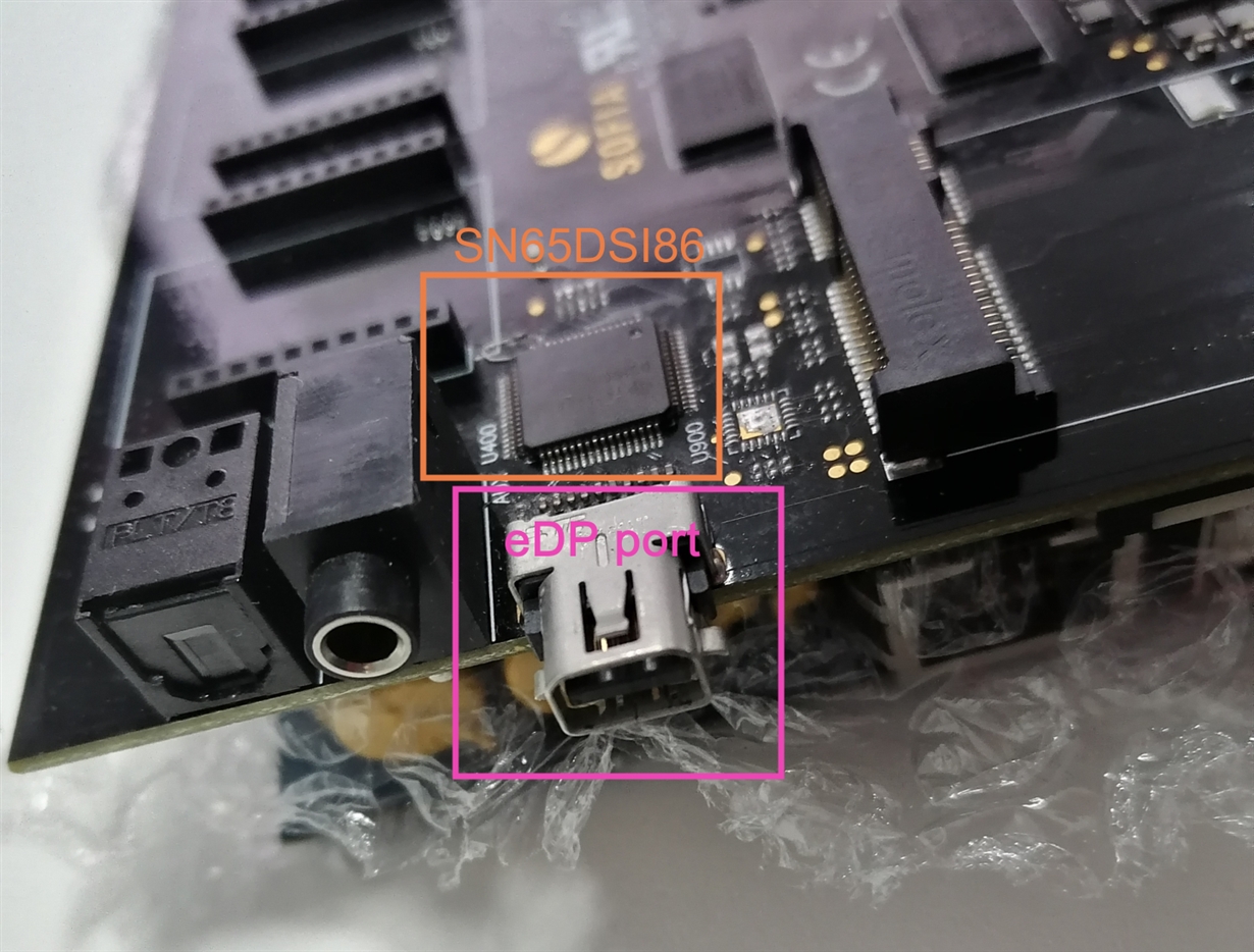
    But the adapter is a simple "thunderbot to HDMI" adapter, because the port on our board is a thunderbolt port just like in Apple's products, here is a picture of our board:

    Is that will work for us?

    Or we need to work with the standard 30pins EDP panels?

    Thanks,

    Talel

  • Talel

    My understanding is that the Thunderbolt combines the two high-performance standards, PCI Express and Mini DisplayPort into a single connection and cable. In this case, you need to make sure the adapter is active, not passive.

    Do you have a mini or DP monitor that can be plugged into the Thunderbolt port?

    Thanks

    David

  • Hi David,

    For the moment we don't have a thunderbolt display, is only Apple has thunderbolt displays? Do you have another recommendation?

    Also we don't have an active Adapter, so I found one, here is its description only for you to confirm it for me (Because I don't know if publishing another products here is against the rules):

    Mini-DisplayPort to HDMI Active Adapter
    - Mini-DisplayPort male to HDMI female, 4K at 60 Hz,
    - Connects a mini-DisplayPort source to an HDMI display cable
    - Sends a single, high-quality active signal to an HDMI display - Perfect for multi-screen displays, and for Single Large Surface (SLS) applications
    - Active adapter (signal regeneration) which allows to exceed the limits of non-DP ++ graphics / video cards (dual-mode), in order to ensure the best possible connection to Ultra HD screens / projectors / etc
    Connectors
    - (1) 20 pin male Mini-DisplayPort
    - (1) 19 pin female HDMI contact

    Thanks again for the great support.

    Talel

  • Talel

    This looks to be an active Mini-DP to HDMI active adapter.

    But you don't need a Thunderbolt display. Any DP display with the mini-DP to DP adapter or Mini-DP display will also work.

    Thanks
    David

  • Hi David,

    Thanks for the confirmation, I'm currently waiting for the new active adapter to come,

    If the adapter is active the expected result should be that the STATUS register must change to 0x01 after requesting the EDID information ?

    Thanks,

    Talel

  • Talel

    Register 0xF8 is LT_PASS. This field is set whenever the EDID is read and then the Semi-Auto link training successfully trains the DisplayPort Link.

    Thanks

    David

  •  hi,T
    ALEL BELHADJ SALEM

    how did you solve i2c detection issue.

    we are facing same issue

    we are not able to detect dsi86 address.

    please help to me to sovle it

    thanks.

    here is my schematic

    mipiedp.pdf

  • Hi,

    Please see my response in this e2e thread: e2e.ti.com/.../965565.

    Thanks

    David

  • Hi David,

    First of all I wish a happy year for you and for all TI stuff.

    In the past days I was waiting until the new active eDP/HDMI adapter arrived.

    The good news:

    • AUXN is about 3V
    • AUXP is about 0V (should it be ~0.3V?)
    • When I plug the HDMI display it goes directly HDMI mode trying to detect something

    Bad news is that, when running same script again to read EDID the DSI86_AUX_STATUS(0xF4) stays 0x00, even 0xF8 is 0x00.

    I'm currently understanding more the datasheet.

    What should I do to read the EDID?

    Or should I just set specific EDID directly and test?

    Thanks,

    Talel

  • Talel

    Can you follow this example and see if you can read out the monitor EDID?

    Example of Indirect I2C Read of the EDID.

    1. Program the AUX_CMD = 0x4, AUX_ADDR[7:0] = 0x50, and AUX_LENGTH = 0x00.

    2. Set the SEND bit.

    3. The SN65DSI86 will clear the SEND bit once the Request has been ACKed.

    4. If SEND_INT_EN is enabled and IRQ_EN is enabled, an IRQ will be asserted. GPU should make sure no

    error flags are set. If no error flags are set, GPU should clear the SEND_INT flag and go to step 5.

    5. Program the AUX_CMD = 0x4, AUX_ADD[7:0] = 0x50, AUX_LENGTH = 0x01, and AUX_WDATA0 = 0x00.

    6. Set the SEND bit.

    7. The SN65DSI86 will clear the SEND bit once the Request has been ACKed.

    8. If SEND_INT_EN is enabled and IRQ_EN is enabled, an IRQ will be asserted. GPU should make sure no

    error flags are set. If no error flags are set, GPU should clear the SEND_INT flag and go to step 9.

    9. Program the AUX_CMD = 0x5, AUX_ADDR[7:0] = 0x50, and AUX_LENGTH = 0x00.

    10.Set the SEND bit.

    11.The SN65DSI86 will clear the SEND bit once the Request has been ACKed.

    12.If SEND_INT_EN is enabled and IRQ_EN is enabled, an IRQ will be asserted. GPU should make sure no

    error flags are set. If no error flags are set, GPU should clear the SEND_INT flag and go to step 13.

    13.Program the AUX_CMD = 0x5, AUX_ADDR[7:0] = 0x50, and AUX_LENGTH = 0x10.

    14.Set the SEND bit.

    15.The SN65DSI86 will clear the SEND bit once the Request has been ACKed.

    16.If SEND_INT_EN is enabled and IRQ_EN is enabled, an IRQ will be asserted. GPU should make sure no

    error flags are set. If no error flags are set, GPU should clear the SEND_INT flag, read data from

    AUX_RDATA0 through AUX_DATA15, and go to step 13.

    17.If read of EDID is complete, the go to step 18. If read of EDID is not complete, then go to Step 13.

    18.Program the AUX_CMD = 0x1, AUX_ADDR[7:0] = 0x50, and AUX_LENGTH = 0x00.

    19.Set the SEND bit.

    20.The SN65DSI86 will clear the SEND bit once the Request has been ACKed.

    21.If SEND_INT_EN is enabled and IRQ_EN is enabled, an IRQ will be asserted. GPU should make sure no

    error flags are set. If no error flags are set, GPU should clear the SEND_INT flag and go to step 22.

    22.Read of EDID finished.

    Thanks

    David

  • Hi David

    Thanks for the suggestion, I'm working on that.

    But I have another question about the problem, the problem is that the driver failed at finding panel:

    ret = drm_of_find_panel_or_bridge(pdata->dev->of_node, 1, 0,
    					  &pdata->panel, NULL);
    	if (ret) {
    		DRM_ERROR("could not find any panel node\n");
    		return ret;
    	}

    it is failing in that step before proceeding to attach or enable the sn65dsi86 bridge.

    The function is looking for a panel or bridge in the device tree source file.

    Is my doubt correct? Or is there a way to check my device tree source? Or request a correct device tree file from someone who successfully made the SN65DSI86 work with some panel?

    Here is my device tree block:

    sn65_bridge: sn65dsi86@2c {
            #address-cells = <1>;
            #size-cells = <0>;
            compatible = "ti,sn65dsi86";
            reg = <0x2c>;
            ti,dsi-lanes = <4>;
            max,dsi-channel = <1>;
            ti,dp-lanes = <2>;
            status = "okay";
            enable-gpios = <&gpio1 9 GPIO_ACTIVE_HIGH>;
            interrupts-extended = <&gpio1 10 IRQ_TYPE_EDGE_FALLING>;
            vccio-supply = <&ldo6_reg>;   //1.8V
            vcca-supply = <&buck1_reg>;   //1.2V
            vpll-supply = <&ldo6_reg>;    //1.8V
            vcc-supply = <&buck1_reg>;    //1.2V
            clock-names = "refclk";
            clocks = <&clk IMX8MM_CLK_DSI_CORE>,
                     <&clk IMX8MM_CLK_DSI_PHY_REF>;
            panel@0 {
                reg = <0>;
                pinctrl-0 = <&pinctrl_mipi_dsi_en>;
                enable-gpio = <&gpio1 9 GPIO_ACTIVE_HIGH>;
                panel-width-mm = <68>;
                panel-height-mm = <130>;
                port {
                    panel1_in: endpoint {
                        remote-endpoint = <&sn65_out>;
                    };
                };
            };
            ports {
                #address-cells = <1>;
                #size-cells = <0>;
                port@0 {
                    reg = <0>;
                    sn65_in: endpoint {
                        remote-endpoint = <&dsim_to_sn65>;
                    };
                };
                port@1 {
                    reg = <1>;
                    sn65_out: endpoint {
                        data-lanes = <0 1 2 3>;
                        lane-polarities = <0 1 0 1>;
                        remote-endpoint = <&panel1_in>;
                    };
                };
            };
            
        };

    Thanks,

    Talel

  • Talel

    Since the driver did not come from TI, I honestly don't know how to solve the issue of driver failing to find the panel.

    Thanks
    David

  • Hi David,

    Thanks for the reply.

    For the moment, I'm working on writing the program to configure SN65DSI86 from Linux user space.

    I have one question: if SN65DSI86 reads EDID correctly, does it program it automatically into the registers ?

    Thanks,

    Talel

  • Talel

    No, the source has to read the monitor EDID through the DSI86 using the I2C-over-AUX method and then program the DSI86 registers accordingly.

    Thanks

    David

  • Hi David,

    I understand the "Indirect I²C Read of the EDID" method very well. So, I started implementing it in the user space in order to finally read the EDID that is returned and saved in AUX_RDATA0 to AUX_RDATA15 registers.

    The problem is that I'm stuck on step 4 which is the SEND bit is never set back to 0 after:

    1. Program the AUX_CMD = 0x4, AUX_ADDR[7:0] = 0x50, and AUX_LENGTH = 0x00.
    2. Set the SEND bit.
    3. The SN65DSI86 will clear the SEND bit once the Request has been ACKed.

    Do you confirm this:

    • Set registers as mentioned in step 1
    • Set SEND bit which is set register AUX_CMD to 0x41
    • Wait until SEND bit goes back to 0, means that I should find that AUX_CMD=0x00 or 0x40

    because when I follow first 3 steps, AUX_CMD get stuck with 0x41, even when I try to change it manually, the SEND bit get stuck with 1.

    Thanks,

    Talel

  • Talel

    I verified on the DSI86 EVM that the SEND bit will get cleared after step #2. Are you seeing any errors being reported from register 0xF4?

    Thanks

    David

  • Hi David,

    Thanks for the reply,

    0xF4 is always 0x00, which means that:

    • bit 0: (SEND_INT. This field is set whenever the SEND bit transitions from 1 to 0.) is not changing and eve:
    • bit 6: (NAT_I2C_FAIL. This bit is set if the I2C-Over-Aux or Native AUX failed.) is also not changing

    This is the same case as the direct method I tried before and sent it to you when the AUX_STATUS (0xF4) is stuck at 0x00.

    What can be the cause of the problem?

    Thanks,

    Talel

  • Talel

    Do you have a I2C bus analyzer that can snoop the I2C bus or maybe use the scope to capture and then manually decode the I2C traffic?

    Below is my I2C command

    <aardvark>

    <configure i2c="1" spi="1" gpio="0" tpower="1" pullups="1" />

    <i2c_bitrate khz="100" />

    ======Clear Register 0xF4======

    <i2c_write addr="0x2D" count="1" radix="16">F4 FF</i2c_write> />

    ======Make sure register 0xF4 is cleared======

    <i2c_write addr="0x2D" count="0" radix="16">F4</i2c_write> />

    <i2c_read addr="0x2D" count="1" radix="16">00</i2c_read> />

    ======Program AUX_CMD=0x4======

    <i2c_write addr="0x2D" count="1" radix="16">78 40</i2c_write> />

    <i2c_write addr="0x2D" count="1" radix="16">76 50</i2c_write> />

    <i2c_write addr="0x2D" count="1" radix="16">77 00</i2c_write> />

    ======Send======

    <i2c_write addr="0x2D" count="1" radix="16">78 41</i2c_write> />

    ======Make sure SEND_INT is set and no errors======

    <i2c_write addr="0x2D" count="0" radix="16">F4</i2c_write> />

    <i2c_read addr="0x2D" count="1" radix="16">00</i2c_read> />

    ======Make sure SEND bit is cleared======

    <i2c_write addr="0x2D" count="0" radix="16">78</i2c_write> />

    <i2c_read addr="0x2D" count="1" radix="16">00</i2c_read> />

    </aardvark>

    Use an I2C analyzer, both register 0xF4 and 0x78 are read back correctly.

    DSI86_I2C_Traffic.csv

    Thanks

    David

  • Talel

    Do you have a I2C bus analyzer that can snoop the I2C bus or maybe use the scope to capture and then manually decode the I2C traffic?

    Below is my I2C command

    <aardvark>

    <configure i2c="1" spi="1" gpio="0" tpower="1" pullups="1" />

    <i2c_bitrate khz="100" />

    ======Clear Register 0xF4======

    <i2c_write addr="0x2D" count="1" radix="16">F4 FF</i2c_write> />

    ======Make sure register 0xF4 is cleared======

    <i2c_write addr="0x2D" count="0" radix="16">F4</i2c_write> />

    <i2c_read addr="0x2D" count="1" radix="16">00</i2c_read> />

    ======Program AUX_CMD=0x4======

    <i2c_write addr="0x2D" count="1" radix="16">78 40</i2c_write> />

    <i2c_write addr="0x2D" count="1" radix="16">76 50</i2c_write> />

    <i2c_write addr="0x2D" count="1" radix="16">77 00</i2c_write> />

    ======Send======

    <i2c_write addr="0x2D" count="1" radix="16">78 41</i2c_write> />

    ======Make sure SEND_INT is set and no errors======

    <i2c_write addr="0x2D" count="0" radix="16">F4</i2c_write> />

    <i2c_read addr="0x2D" count="1" radix="16">00</i2c_read> />

    ======Make sure SEND bit is cleared======

    <i2c_write addr="0x2D" count="0" radix="16">78</i2c_write> />

    <i2c_read addr="0x2D" count="1" radix="16">00</i2c_read> />

    </aardvark>

    Use an I2C analyzer, both register 0xF4 and 0x78 are read back correctly.

    5773.DSI86_I2C_Traffic.csv

    Thanks

    David