This thread has been locked.

If you have a related question, please click the "Ask a related question" button in the top right corner. The newly created question will be automatically linked to this question.

TUSB216: TUSB216 I2C Mode Unexpected Initial CFG_ACTIVE Value and No Signal Change After EQ/DC Boost Configuration

Part Number: TUSB216
Other Parts Discussed in Thread: TUSB214, , TUSB214EVM,

Tool/software:

DearTi,

We are currently testing the TUSB214 in I²C mode based on the procedure outlined in the datasheet and TI E2E forum threads. However, we have encountered two issues and would like your support:

our schematic layout:

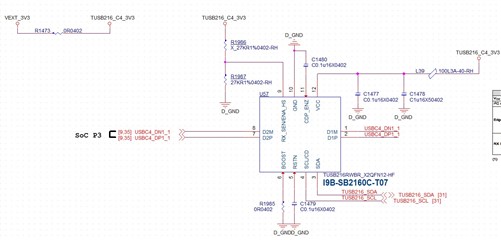
We are currently evaluating TUSB216, but due to sample availability, we are conducting preliminary I²C functionality testing using the similar TUSB214 device.

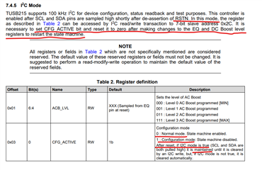
1. Unexpected Initial Value of Register 0x03 (CFG_ACTIVE) after RESET

According to the datasheet (section 7.4.5) and another thread in forum (see Ryan Kitto’s post)

Although schematic put TUSB216 , due to 

tusb214 datasheet:

https://www.ti.com/lit/ds/symlink/tusb214.pdf?ts=1748421012763&ref_url=https%253A%252F%252Fti.com%252Fproduct%252FTUSB214

and another E2E thread

https://e2e.ti.com/support/interface-group/interface/f/interface-forum/1272265/tusb212-interface-forum-tusb212-control-via-i2c

the expected behavior mentioned in thread by Ryan  and datasheet are :

  • After RSTN toggle and entering I²C mode, register 0x03 should return 0x35, meaning bit 0 is set (Configuration Mode).

  • After configuration, clear bit 0 to 0, making 0x03 = 0x34, thus enabling the state machine.

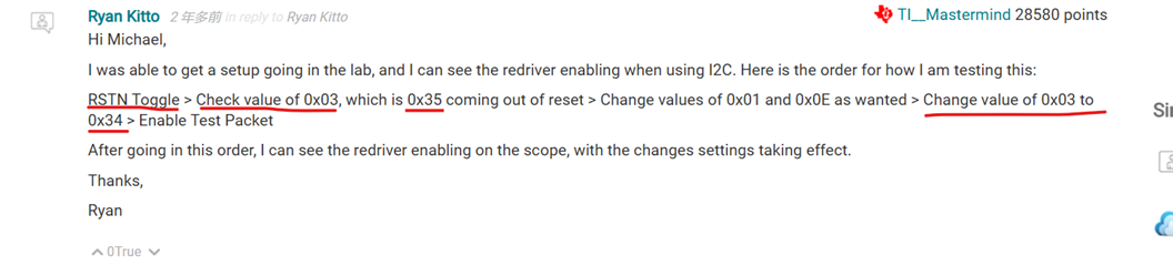
However, on our board, after RESET and entering I²C mode, we observed that:

  • 0x03 returns 0x74, meaning bit 0 is already 0 (Normal Mode).

  • This contradicts the spec, which states bit 0 should be 1 by default in I²C mode.

Could you clarify why 0x03 shows 0x74 instead of the expected 0x35 after reset?

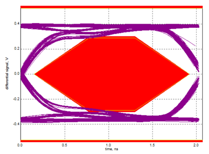
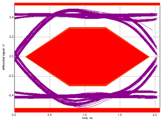
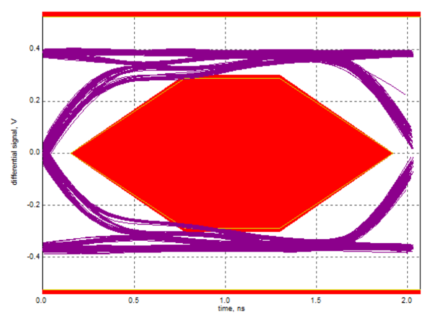
2. EQ/DC Settings Have No Effect on USB Signal Eye Pattern

I wrote an I²C script to automate register writes:

  • 0x03 set to 0x75 (Configuration Mode)

  • 0x01 (EQ Boost) set to 0x07 (Level 3)

  • 0x0E (DC Boost) set to 0x05 (60mV)

  • 0x03 set back to 0x74 (Normal Mode)

    ======== TUSB216 Initialization Log ========
    [BEFORE enter active mode] cfg_active:
    0x74
    [AFTER enter active mode] cfg_active:
    0x75
    [SETTINGS] Set eq_boost = 3
    [SETTINGS] Set dc_boost = 60 mV
    [BEFORE exit active mode] eq_boost:
    0x7 (Level 3 (MAX))
    [BEFORE exit active mode] dc_boost:
    0x5 (60mV)
    [AFTER exit active mode] cfg_active:
    0x74
    [AFTER exit active mode] eq_boost:
    0x7 (Level 3 (MAX))
    [AFTER exit active mode] dc_boost:
    0x5 (60mV)
    ======== TUSB216 Log Done ========
    

Despite the register changes, there is no observed improvement or change in the USB signal eye pattern, while the same hardware wired in strap mode (non-I²C) does show the expected enhancement.


Please help to clearify these two question.

Thanks

  • HI Wiser,

    I'd just like to confirm a few things on your setup. First, do you have the correct pull-ups on the SDA/SCL lines? I don't see them on the schematic, so I would like to confirm these are implemented.

    Next, when you are using I2C, before you set the CFG _Active bit to 1, what is the default value of that register? Please make sure you are only adjusting the CFG_ACTIVE bit of that register. 

    What is the status of the CD/ENA_HS pins if the device is set to not active mode. Like you said, at start-up, if the SDA/SCL pins see pull-ups on the I2C lines, the device should start in I2C mode, so if it is not, it may be that the SDA/SCL pins aren't seeing the I2C lines.

    Could you confirm that you can read back any writes you make over I2C and double check they are being set?

    Despite the register changes, there is no observed improvement or change in the USB signal eye pattern, while the same hardware wired in strap mode (non-I²C) does show the expected enhancement.

    Is the redriver on at all in I2C mode, or only in pin-strap mode? Switching back and forth between 0 and 1 on the CFG_ACTIVE bit has no effect on the signal at all?

    Thanks,

    Ryan

  • Hi Ryan,

    Thanks for your response and clarification.

    1. Regarding the initial value of CFG_ACTIVE:

    After retesting on the TUSB214 board, we can disregard the initial CFG_ACTIVE = 0 concern.
    We confirmed that right after reset, the value of register 0x03 is 0x75, which means the device is correctly entering configuration mode (bit 0 = 1) in I²C mode.

    2. I²C bus status:

    . First, do you have the correct pull-ups on the SDA/SCL lines? I don't see them on the schematic,

    SDA and SCL are pulled high  ,  pull high resistors are located at other schematic around host I2C bus , and we can successfully perform I²C read/write operations (e.g., dumping and write and read back register 0x01, 0x03, 0x0E), so the device should enter I²C mode correctly
    We are using an MTK SoC running Android OS as the I²C master.
    The logs provided previously , labeled "TUSB216 Initialization Log" are generated via I²C transactions , controlled by i2c read/write functions included in script

    #!/system/bin/sh
    
    LOG_FILE="/data/local/tmp/duvel_debug.log"
    CFG_NODE="/sys/devices/platform/11e03000.i2c/i2c-3/3-002c/cfg_active"
    EQ_NODE="/sys/devices/platform/11e03000.i2c/i2c-3/3-002c/eq_boost"
    DC_NODE="/sys/devices/platform/11e03000.i2c/i2c-3/3-002c/dc_boost"
    
    EQ_VALUE="$1"  # EQ boost level: 0/1/2/3
    DC_VALUE="$2"  # DC boost in mV: 40/60/80
    
    if [ "$EQ_VALUE" = "" ] || [ "$DC_VALUE" = "" ]; then
      echo "Usage: $0 <eq_boost_level (0~3)> <dc_boost_mv (40|60|80)>"
      exit 1
    fi
    
    echo "======== TUSB216 Initialization Log ========" >> "$LOG_FILE"
    echo "======== TUSB216 Initialization Log ========"
    echo "[BEFORE enter active mode] cfg_active:" >> "$LOG_FILE"
    cat "$CFG_NODE" >> "$LOG_FILE"
    
    echo 1 > "$CFG_NODE"
    
    echo "[AFTER enter active mode] cfg_active:" >> "$LOG_FILE"
    cat "$CFG_NODE" >> "$LOG_FILE"
    
    echo "[SETTINGS] Set eq_boost = $EQ_VALUE" >> "$LOG_FILE"
    echo "$EQ_VALUE" > "$EQ_NODE"
    echo "[SETTINGS] Set dc_boost = $DC_VALUE mV" >> "$LOG_FILE"
    echo "$DC_VALUE" > "$DC_NODE"
    
    echo "[BEFORE exit active mode] eq_boost:" >> "$LOG_FILE"
    cat "$EQ_NODE" >> "$LOG_FILE"
    echo "[BEFORE exit active mode] dc_boost:" >> "$LOG_FILE"
    cat "$DC_NODE" >> "$LOG_FILE"
    
    echo 0 > "$CFG_NODE"
    
    echo "[AFTER exit active mode] cfg_active:" >> "$LOG_FILE"
    cat "$CFG_NODE" >> "$LOG_FILE"
    echo "[AFTER exit active mode] eq_boost:" >> "$LOG_FILE"
    cat "$EQ_NODE" >> "$LOG_FILE"
    echo "[AFTER exit active mode] dc_boost:" >> "$LOG_FILE"
    cat "$DC_NODE" >> "$LOG_FILE"
    
    echo "======== TUSB216 Log Done ========" >> "$LOG_FILE"
    echo "======== TUSB216 Log Done ========"

    3. ENA_HS signal behavior:

    What is the status of the CD/ENA_HS pins if the device is set to not active mode.

    We monitored the ENA_HS pin after returning to normal mode (bit 0 = 0), but its voltage level did not change — it remained low.
    We’d like to confirm:

    In I²C mode, is the ENA_HS pin expected to function the same as in pin-strap mode (like shows in attached schematic )?
    Or is it not necessary to include pull-up/down resistors on this pin in I²C mode (as shown in the schematic originally designed for pin-strap control)?

    4. No observable signal effect:

    Is the redriver on at all in I2C mode, or only in pin-strap mode? Switching back and forth between 0 and 1 on the CFG_ACTIVE bit has no effect on the signal at all?

    Yes — as you suspected — even though we toggle CFG_ACTIVE between 1 and 0 as specified:

    The EQ boost and DC boost register values are set correctly, and

    We can confirm via read-back that the values persist.

    However, we observe no effect on the USB signal (eye pattern remains the same).


    Wiser

  • Hi Wiser,

    In I²C mode, is the ENA_HS pin expected to function the same as in pin-strap mode (like shows in attached schematic )?
    Or is it not necessary to include pull-up/down resistors on this pin in I²C mode (as shown in the schematic originally designed for pin-strap control)?

    I double checked it, you're right, this pin doesn't have the same functionality in I2C mode. You can leave the Pull-up/pull-downs if you want, as these will determine the starting value for DC_Boost. Otherwise, you don't need to monitor this pin.

    One question I have, just to confirm for sequencing and test procedure, are you using XHSETT to send out test packets through the USB2 lines? When you are sending the test packets, are you waiting until AFTER the TUSB214 is taken out of config mode, or are you sending the packets, and then enabling the TUSB214/taking it out of config mode? The TUSB214 needs to be powered and taken out of config mode I believe for testing.

    If possible, you could also test using a TUSB216EVM or TUSB214EVM to see if you have issues with our EVMs as well?

    Thanks,

    Ryan

  • Hi Ryan,

    We took some additional tests on TUSB214 comparing the behavior between pin-strap mode and I²C mode when adjusting DC Boost .  
    Below are the results.


     Pin-Strap Mode Results

    When using external resistors to set DC Boost and EQ:

    • DC Boost = 80 mV (RDC1 = DNI, RDC2 = 47 kΩ), EQ0 (REQ = 100 Ω):
      ➜ The USB eye diagram shows clear signal improvement — attached scope screenshot.

      Pin Strap mode 80mV
    • DC Boost = 40 mV (RDC1 = 47 kΩ, RDC2 = DNI), EQ0 (REQ = DNI):
      ➜ The USB eye diagram again changes accordingly — attached scope screenshot.


    I²C Mode Results

    When using I²C writes to change DC Boost between 40 mV and 80 mV:

    • The I²C transactions were successful, values in registers were verified by read-back.

    • However, the USB eye diagram remains unchanged, identical to default pin-strap DC Boost = 80 mV condition, even when toggling DC Boost via I²C.


    Additionally, after entering I²C mode,   initial register values by i2c read from 0x01/ 0x0e — please refer below logs  for the register dump.

    and 0x03 is 0x75 , which is keep at CFG_ACTIVE mode while entered i2c mode.

    console:/sys/devices/platform/11e03000.i2c/i2c-3/3-002c #
    at dc_boost                                                                   <
    0x3 (40mV)
    console:/sys/devices/platform/11e03000.i2c/i2c-3/3-002c #
    console:/sys/devices/platform/11e03000.i2c/i2c-3/3-002c #
    at eq_boost                                                                   <
    0x7 (Level 3 (MAX))

    In addition, we will try to obtain an official TUSB214/216 EVB to perform the same tests for comparison.

    If there are any specific debug checks that you would recommend , please feel free to suggest

    Thanks

    Wiser

  • Hi Wiser,

    When using I²C writes to change DC Boost between 40 mV and 80 mV:

    • The I²C transactions were successful, values in registers were verified by read-back.

    • However, the USB eye diagram remains unchanged, identical to default pin-strap DC Boost = 80 mV condition, even when toggling DC Boost via I²C.


    Additionally, after entering I²C mode,   initial register values by i2c read from 0x01/ 0x0e — please refer below logs  for the register dump.

    and 0x03 is 0x75 , which is keep at CFG_ACTIVE mode while entered i2c mode.

    It does look like the redriver is enabling, going by the eye diagram, so thats good. However typically, if the redriver is in I2C mode, I believe the redriver is meant to be disabled when CFG_ACTIVE is high, and then re-enable when the bit is set to 0. If changing any of the bits has no effect, then I wonder if the redriver is entering I2C mode or not. Trying this with both a TUSB216 and TUSB214EVM will help determine whether its a design or device issue potentially.

    Could you try this sequence in the meantime, to double check?

    • Disable test packets, then enable redriver
    • Adjust CFG_ACTIVE from 1 to 0, then back to 1 (optional, feel free to leave this step out)
    • Adjust the values of the registers as desired
    • Take redriver out of Config mode (1 to 0)
    • Send packets.

    You can test with some different sequencing here too, like leaving it in config mode to see if that affects performance.

    • DC Boost = 80 mV (RDC1 = DNI, RDC2 = 47 kΩ), EQ0 (REQ = 100 Ω):
      ➜ The USB eye diagram shows clear signal improvement — attached scope screenshot.

      Pin Strap mode 80mV
    • DC Boost = 40 mV (RDC1 = 47 kΩ, RDC2 = DNI), EQ0 (REQ = DNI):
      ➜ The USB eye diagram again changes accordingly — attached scope screenshot.

    For these, I just want to double check the DC Boost settings. I believe the bottom eye should be the 80mV eye, and the top should be the 40mV eye, going by how they look on the eye diagrams. (More margin typically = higher DC Boost).

    Thanks,

    Ryan

  • Hi Ryan :


    We did another round of testing.
    The following is the I²C operation under our SoC system driver (MTK Android platform):

    Modify DC Boost from 40 mV → 80 mV and then set CFG_ACTIVE bit 0 to 0 (Normal mode).

    We also tried changing EQ Boost levels.

    In both cases, the USB test packet signal remained unchanged — no visible difference on the scope.

    # Read initial DC Boost value (after entering I²C mode)
    cat dc_boost
    --> 0x3 (40 mV)
    
    # Read initial CFG_ACTIVE value
    cat cfg_active
    --> 0x75 (Configuration mode)
    
    # Write DC Boost = 80 mV
    echo 80 > dc_boost
    
    # Read ,confirm updated DC Boost 
    cat dc_boost
    --> 0x7 (80 mV)
    
    # Write , switch to Normal mode
    echo 0 > cfg_active
    
    # Read ,confirm CFG_ACTIVE now is 0x74 (Normal mode)
    cat cfg_active
    --> 0x74

    Could you help review whether our register write sequence is correct for DC BOOST and CFG ACTIVE registers:

    Register Function Bits
    0x01 DC Boost Bits 0 ~ 2
    0x03 CFG_ACTIVE Bit 0
    0x0E EQ Boost Bits 4 ~ 6

    // Write DC Boost = 80 mV
    // DC_BOOST register bits [2:0] , write val= 0x07(80mV) for case in above logs
    ret = regmap_read(data->regmap, TUSB216_REG_DC_BOOST, &val);
    val &= ~GENMASK(2, 0);
    val |= regval;
    ret = regmap_write(data->regmap, TUSB216_REG_DC_BOOST, val);
    
    
    //Switch to Normal mode
    // CFG_ACTIVE register bit 0 ,write val= 0x74(config active) for case in above logs
    ret = regmap_read(data->regmap, TUSB216_REG_CFG_ACTIVE, &val);
    if (on)
        val |= 0x01;
    else
        val &= ~0x01;
    ret = regmap_write(data->regmap, TUSB216_REG_CFG_ACTIVE, val);


    Thanks


    Wiser

  • Hi Wiser,

    I believe the sequencing looks good. If anything, my only recommendation would be to re-write that configuration bit just to make sure the device is in config mode.

    In both cases, the USB test packet signal remained unchanged — no visible difference on the scope.

    Just to confirm, you are turning off the test packets when you are writing to the redriver via I2C, and then re-enabling the test packets when you take the redriver out of I2C mode, correct?

    Thanks,

    Ryan

  • Hi Ryan:

    you are turning off the test packets when you are writing to the redriver via I2C, and then re-enabling the test packets when you take the redriver out of I2C mode, correct?

    Hi Ryan,

    After further checking with our hardware team, we realized that in our previous tests, when adjusting the register values (DC Boost, CFG_ACTIVE), the USB chip was continuously transmitting test packets without restarting — the test packet stream was never interrupted.

    Today, we corrected our test procedure:

    • After modifying DC Boost and CFG_ACTIVE, we now stop and restart the USB test packet transmission to ensure the TUSB214 re-locks and applies the new settings.

    With this corrected procedure, we observed that when changing DC Boost from 40 mV to 80 mV, the USB eye diagram clearly shows larger amplitude — confirming that the redriver is working as expected.


    Thank you very much for your support  
    Wiser

  • Hi Wiser,

    Good to hear! Sequencing with these devices is important to make sure it works properly, so it's good to hear you got it figured out.

    Please let me know if you have any other questions.

    Thanks,

    Ryan