This thread has been locked.

If you have a related question, please click the "Ask a related question" button in the top right corner. The newly created question will be automatically linked to this question.

TCAN1462-Q1: TCAN1462-Q1 topology measurement

Part Number: TCAN1462-Q1

Tool/software:

Hi TI CAN Expert,

I am currently testing below topology using TCAN1462-Q1. 

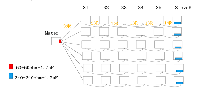
For master talk to slaves, or salves talks to master, CANH/CANL waveform looks OK.

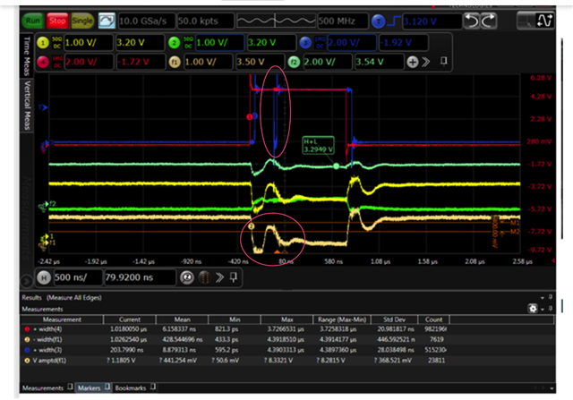
However, if you look at slave talks to slave, the CANH/CANL waveform is quite worse. 

Below is slave S6 TXD input, and measured at S6 RXD output. Yellow one is CANH, and Green one is CANL. Red one is TXD input, blue one is RXD output. 

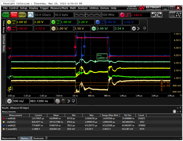
Below is S5 talks to S5. 

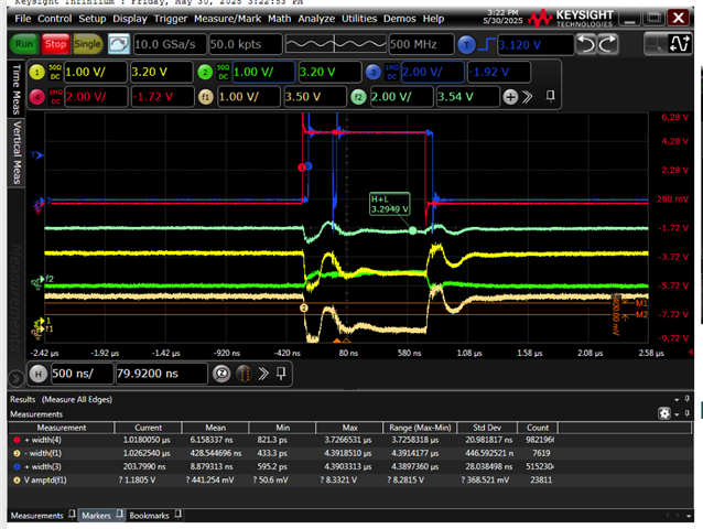
It seems reflection is bad. Do you have any suggestion how to improve this?


Regards

Nic

  • Hi Nic,

    Could you please help clarify what is being referred to as bad reflections?

    I.e., which reflection is causing data errors? Thanks  

    Best Regards,

    Michael  

  • Hi Michael,

    I mean here, where I pointed out using red circle. 

    Regards

    Nic

  • Hi Nic,

    RXD seems to recover per the degraded CAN bus and curios if bit errors are actually not observed. I would recommend  confirming 4.7 nF is used at the end terminal and not 4.7 uF. Degradation, phase delays, reflections are expected. 

    • Could we replace the end termination with a single 120 ohms without the 4.7 uF to verify a cleaner CANH / CANL and RXD observed?
    • Also, when speed is reduced, any significant differences? Thanks.

    Best Regards,

    Michael.

  • Hi Michael,

    Sorry that it is typo. We do use 4.7nF in both master and slave side.

    And the waveform has no change when speed is reduced. 

    Regards

    Nic

  • Hi Nic,

    Thanks for clarifying. I suspect the bus is overloaded, observed as not reaching the expected VOD and would recommend adjusting the blue termination shown in the block diagram.

    • Verify the behavior with termination similar to the red for 60 ohms and then re-adjusting to 120 ohms to verify.
    • Are there any other termination resistors included at multiple nodes not mentioned?
    • With speed reduced, please confirm if the reduced speed implies 500 kbps or lower? 
    • Is RX node far from the device?
    • Are stub lengths < 0.3 m and bus length < 40 m similar to 9.2.2.1 of the data sheet? 
    • Any partial bus shorts on CANH-CANL, CANH-GND, CANL-GND?
    • Are 100 nF decoupling caps placed as close to the power supplies as much as possible? I.e., are the power supplies clean without sags?
    • Also, is the yellow in the block diagram series resistors? If so, would recommend to use the same value at each node and verify.
    • If all the above are confirmed, I would recommend replacing the device with a known good unit to verify, thanks. 

    Best Regards,

    Michael.