This thread has been locked.

If you have a related question, please click the "Ask a related question" button in the top right corner. The newly created question will be automatically linked to this question.

SN65DSI83-Q1: Auto Recovery for DSI83-Q1 after PLL unlock

Part Number: SN65DSI83-Q1

Tool/software:

Hi,

We are facing a similar issue in which we are using the DSI83-Q1 for MIPI to LVDS translation. We are using DSI REFCLK as the reference clock. The attached waveform is start-up sequence. 
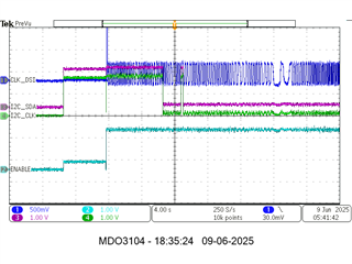
What we are seeing that sometimes the screen goes blank randomly.

We are trying to recreate this issue in the lab and we thought of randomly introducing the jitter to the DSI CLK by shorting it. What we are seeing is that during short sometimes screen auto recovers while sometime it doesn't comeback at all. We have verified the sync times and both DSI and LVDS sync times are same and we don't see issues in startup.

We wanted to understand this in detail -

1. What can be done to avoid this (equalization, LVDS termination) etc. to avoid PLL Unlock.

2. Why the issue automatically recovers sometime while not other times - what can be tuned (if pll lock time etc limit is there) to make it automatically recovering?

  • Hi Mandan,

    How often does this issue occur? Since it is reproducible, in cases where video does not come back up, can you please share the register dumps including 0xE5 error checking register.

    After the issue occurs, please try the following steps and check if the it recovers.

    • Clear and then set the PLL_EN bit,
    • Set the SOFT_RESET bit 


    Have you tested with internal test pattern? Does it show any similar issue with the test pattern or is it only with DSI input?

    If possible, can you add external reference clock and check if this issue occurs. Is there an option on your board to add a reference clock and to enable it?

    Best regards,
    Ikram

  • Hi Ikram,

    The issue seems to often in test bench at random (either thermal noise or electromagnetic noise) is at higher side. We tried to check the 0xE5 register bit and saw that it was giving non 0 value during working mode also. During working condition values were 3D, 35 etc. on different reads while on the non working mode values were 7D, FD etc.

    Yes the issue recovers when we set the PLL and SOFT_RESET.

    But I wanted to know how to detect if there is indeed a true failure on not. I may ignore the PLL_UNLOCK bit as it might be oversensitive to noise but what register values should I read in 0xE5 to understand if a failure has happened indeed or not (which is not over sensitive)

    Also is it necessary to clear the bits (write 0xFF to 0xE5) before reading to understand the failure or the errors get cleared without writing also once respective error is out of fail limits?

    I will share the full register dump and test pattern results sooner.

  • Hi Mandan,

    But I wanted to know how to detect if there is indeed a true failure on not. I may ignore the PLL_UNLOCK bit as it might be oversensitive to noise but what register values should I read in 0xE5 to understand if a failure has happened indeed or not (which is not over sensitive)

    Also is it necessary to clear the bits (write 0xFF to 0xE5) before reading to understand the failure or the errors get cleared without writing also once respective error is out of fail limits?

    Yes, please check the "7.4.2 Initialization Sequence" to write 0xFF to register 0xE5 to clear the error checking register. Then read the register on startup during working conditions, and get register dump when the issue occurs.

    Please also test with internal test pattern to verify that the downstream LVDS connection is valid when DSI input is not used.

    Best regards,
    Ikram

  • Hi Ikram,

    When we have used the test pattern generation - the issue has not reproduced on its own, however if we short the clock lines the issue reproduces i.e. it doesn't recover automatically. This means that there is definitely something wrong with the clock recovery on the DSI side itself as the LVDS side seems pretty stable.

    We have tried to update the CSR registers also but still we are seeing the blank screen which doesn't auto recovers meaning there is definitely something wrong with PLL lock. I am attaching the CSR register list here along with the panel information

    CSR tool generated


    0x09              0x00
    0x0A              0x01
    0x0B              0x00 // was 0x00
    0x0D              0x00 // PLL enable
    0x10              0x26
    0x11              0x00
    0x12              0x11
    0x13              0x00
    0x18              0x78
    0x19              0x00
    0x1A              0x03
    0x1B              0x00
    0x20              0x20
    0x21              0x03
    0x22              0x00
    0x23              0x00
    0x24              0x00 // E0 for Test Pattern 
    0x25              0x00 // 01 for Test Pattern
    0x26              0x00
    0x27              0x00
    0x28              0x14 // was 0x21 
    0x29              0x07 // was 0x00
    0x2A              0x00
    0x2B              0x00
    0x2C              0x30
    0x2D              0x00
    0x2E              0x00
    0x2F              0x00
    0x30              0x01
    0x31              0x00
    0x32              0x00
    0x33              0x00
    0x34              0x28
    0x35              0x00
    0x36              0x1f
    0x37              0x00
    0x38              0x28
    0x39              0x00
    0x3A              0x0d
    0x3B              0x00
    0x3C              0x00
    0x3D              0x00
    0x3E              0x00

    Panel Information -

     Panel Info

    Also we are not able to figure out an effective way for the feedback to be use full as the register 0xE5 anyway gives errors in working scenario as well. Like even when screen works perfectly, 0xE5 registers are non zero - so we are not able to implement a feedback loop on when to run PLL_EN and SOFT_RST.

    Can you let us understand how we should implement this error checking loop for better understanding of true failure case and can have the PLL locked state?

  • Hi Mandan,

    1. How are you calculating the DSI clock frequency to LVDS clock? 

    The equation with the DSI83 using 4 DSI lanes would be:

    - DSI CLK = (LVDS_CLK * bpp)/(2 * no_of_DSI_lanes)
    - or LVDS_CLK  = (DSI CLK * 2 * no_of_DSI_lanes)/bpp = (87.7 MHz * 2 * 4)/24 = 51.158 MHz 29.233 MHz (corrected)

    Please update the LVDS and DSI clock rates and test this. What rate is the DSI clock input from the video source? 

    2. Also, are you clearing the 0xE5 register at the start? Please clear and then check if there are any errors during runtime in working and issue conditions.

    3. Please verify that the initialization sequence from the datasheet is followed ("8.4.2 Power-Up Sequence"). 

    4. Are the DSI settings such as LP, burst mode and sync mode programmed the same for DSI source and the DSI86 bridge?


    Best regards,
    Ikram

  • Hi Ikram,

    1. We have updated the clock settings as well, However please note that the clock division is incorrect - it should be 29.233MHz(928*525*60) rather not 51.158 MHz.(87.7*8/24=87.7/3=29.23)  I am attaching the panel information here along with.

      We are using Format 2 with 24bit LVDS panel
      Below are attached snapshot for panel information.


      After we have updated the correct clock values and sync delay etc. - it seems to be working fine and we do not see any errors in 0xE5.

    2. We are clearing 0xE5 as part of the init sequence. 

    3. we have verified for the same and a snapshot is attached for the same in the beginning of the post - however we do not have a way to know the HS mode start time - so we have tried to put a fixed delay in writing 0xFF to register 0xE5 after the enable of transmission of video stream.

    4. We are using qcom,mdss-dsi-traffic-mode = "non_burst_sync_event" - I have changed the settings from Burst to non burst but it does not create any difference in the generated CSR registers from the DSI Tuner tool. I have attached the dts file along with for the MIPI DSI Source.

    Additionally-

    1. The DSI tool generates few extra set of registers which are not in datasheet (0x13, 0x26, 0x27, 0x2A, 0x2B, 0x2E, 0x2F, 0x32, 0x33, 0x35, 0x37, 0x39, 0x3B, 0x3D, 0x3E)- so we have removed it.

    Attached is the list of registers and settings which have worked for us and a general guide line to whoever is facing the issue on the same.

    for ref only - (800x480)
    DSI Clock= HVFPS = 928x525x60= 23.232MHz
    LVDS Clock= DSI Clock*24(bpp)/2(DDR)*4(Lanes)= 87.696MHz
    
    EN toggle
    
    10ms delay
    
    0x0A              0x01
    0x0B              0x10
    0x10              0x26
    0x11              0x00
    0x12              0x11
    0x18              0x78
    0x19              0x00
    0x1A              0x03
    0x1B              0x00
    0x20              0x20
    0x21              0x03
    0x28              0x21
    0x29              0x00
    0x2C              0x30
    0x2D              0x00
    0x30              0x01
    0x31              0x00
    0x34              0x28
    0xE0              0x01
    0xE1              0xFE (ignore PLL unlock as it is sensitive, If all the time 0xE5=01 and display indeed goes blank we can write FF)
    
    10ms delay
    
    0x0D              0x01 // PLL enable
    
    10ms delay
    
    0x09              0x00 // Soft Reset
    
    wait for DSI source to start streaming(maybe give 750ms -900ms delay- this will not hinder in display coming up -rather monitoring error- if error happens during this period ignore)
    
    0xE5          0xFF
    
    start observing INT gpio or 0xE5 for further errors here onwards

    This has cleared all errors on the config registers however, we can still see that auto recovery doesn't happen if fault is introduced. Is this normal in the SN65DSI83-Q1 use case?

  • Hi Mandan,

    Does the REFCLK frequency match the LVDS frequency with multiplier? There could be an issue if the line time is mismatched between DSI settings and LVDS.


    https://e2e.ti.com/support/interface-group/interface/f/interface-forum/1454763/sn65dsi83-q1-how-to-recovery-auto-when-error-detect-at-the-mipi-dsi-input/

    According to this previous E2E, after an error such as PLL unlock the best solution would be to restart the device and follow the initialization procedure again.

    Is the issue still randomly occurring or is it only when you externally introduce jitter?

    Best regards,
    Ikram

  • Hi Ikram,

    We are using DSI clock only as getting the exact divider for REF CLCK might be little difficult and will add some extra cost.

    We will do a functional testing on a larger no and understand the nature of failure - as of now it seems random/ when motor noise is higher in the vehicle. However be the mode of failure as external introduced jitter or random - one thing is evident that it doesn't recover automatically.

  • Hi Mandan, 

    Please let us know if you are able to test and recreate the failure. It should not PLL unlock randomly unless there is an issue with the input or other system-level factor.

    It could be related to jitter or noise on the clock not meeting the datasheet specifications. And to recover after PLL unlock, the system should be reinitialized through the power-up and initialization procedure.

    Let us know if you find any further information/test results about this or have any questions.

    Best regards,
    Ikram