This thread has been locked.

If you have a related question, please click the "Ask a related question" button in the top right corner. The newly created question will be automatically linked to this question.

TMDS1204: Current Consumption

Part Number: TMDS1204
Other Parts Discussed in Thread: TMUXHS4612, TMUXHS4212, TDP2004

Tool/software:

Hi Team,

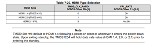
Please provide the maximum current consumption details of TMDS1204RNQR for HDMI 2.1 FRL configuration, with VIO voltage level being 3.3V.

Thanks

  • Hi,

    For HDMI FRL 12Gbps, with TMDS1204 in limited mode and DC coupled TX/RX, the max power consumption is 775mW.

    Thanks

    David

  • Hi David,

    If you are stating this referring section 5.5 in datasheet, they have mentioned it as power dissipation and not power consumption. Could you please clarify on this?

    Thanks

  • Hi,

    I am referring to section 5.5 of the TMDS1204 datasheet and I should say power dissipation instead consumption in my previous response to minimize the confusion.

    Thanks

    David

  • Hi David,

    What will be the current consumption for the same configuration?

    Thanks

  • Hi,

    The current consumption is around 215mA.

    Thanks

    David

  • Hi David,

    1. Is current consumption data mentioned in datasheet?

    2. Also since the HBM of IC is +/- 4kV, is an ESD IC required for data pins?

    Thanks

  • Hi,

    Please see my response below

    1. Is current consumption data mentioned in datasheet?

    No, we only listed typical power dissipation number in the datasheet. For the worst current consumption, I took the worst current power dissipation and divide by 3.6V VCC since the worst power dissipation is collected at 3.6V 

    2. Also since the HBM of IC is +/- 4kV, is an ESD IC required for data pins?

    When you ask if the ESD IC is required, I assume you are referring to the IEC 61000-4-2. The HBM and IEC 61000-4-2 are two different standard. The HBM standard is intended to simulate a charged person discharging to ground through the circuit under test in the manufacturing environment. The IEC 61000-4-2. is the standard for system level ESD testing and it is more stringent than the HBM standard. In order to meet the IEC 61000-4-2 requirement, you would need an external ESD IC. Please see TMDS1204 datasheet for ESD IC recommendation. 

    Thanks

    David

  • Hi David,

    1. Since there isn't any circuit mentioned for RX_DETECT signal, can we consider SIGDET_OUT pin for RX_DETECT signal?

    2. How to configure Redriver for particular specification like 1.4, 2.0 or 2.1, can we do it manually using pinstrap options or does the redriver detect it?

    Thanks

  • Hi,

    1. Since there isn't any circuit mentioned for RX_DETECT signal, can we consider SIGDET_OUT pin for RX_DETECT signal?

    Yes, SIGDET_OUT is an open drain output asserted low when signal is detected on IN_CLK or IN_D2 when HPD_IN is high.

    2. How to configure Redriver for particular specification like 1.4, 2.0 or 2.1, can we do it manually using pinstrap options or does the redriver detect it?

    TMDS1204 monitors offsets 20h and 31h using DDC snooping to determine HDMI type as either HDMI 1.4, HDMI 2.0, or HDMI 2.1 FRL.

    Thanks
    David

  • Hi David,

    1. For sink application, fanout buffer is provided in the IC due to which we can use both TMDS and FRL signaling. In this case, does the IC determine signalling scheme through DDC snooping?

    2. For source application, since the fanout buffer provided is not bidirectional we cannot use both TMDS and FRL signaling, one way to use both is by using an external MUX for TMDS clock signal and FRL Data_3 signal or is there any other way to implement both signaling scheme? If it has to be done through external MUX, does TI have any MUX that supports HDMI 2.1 with single input and 2 output channels.

    3. For both source and sink application, is there a pin strap configuration where I can use both TMDS and FRL signaling scheme without repeatedly changing the configuration?

    Thanks

  • Hi,

    1. For sink application, fanout buffer is provided in the IC due to which we can use both TMDS and FRL signaling. In this case, does the IC determine signalling scheme through DDC snooping?

    Yes, when the fan-out buffer feature is enabled, the TMDS1204 will output the HDMI clock on RCLKOUTp/n when operating in HDMI 1.4 or HDMI 2.0. The OUT_CLKp/n will be disabled. When operating in HDMI 2.1 FRL mode, the TMDS1204 will output FRL data3 on OUT_CLKp/n. RCLKOUTp/n will be disabled. TMDS1204 monitors offsets 20h and 31h using DDC snooping to determine HDMI type as either HDMI 1.4, HDMI 2.0, or HDMI 2.1 FRL.

    2. For source application, since the fanout buffer provided is not bidirectional we cannot use both TMDS and FRL signaling, one way to use both is by using an external MUX for TMDS clock signal and FRL Data_3 signal or is there any other way to implement both signaling scheme? If it has to be done through external MUX, does TI have any MUX that supports HDMI 2.1 with single input and 2 output channels.

    You can use TMUXHS4612 as a possible solution. But I never see a source that does not support both TMDS and FRL.

    3. For both source and sink application, is there a pin strap configuration where I can use both TMDS and FRL signaling scheme without repeatedly changing the configuration?

    Can you list out the features you want to implement for both the source and the sink application. I can see if there is a pin strap mode that can cover both cases.

    Thanks

    David

  • Hi David,

    1. For source application, FPGA supports both TMDS and FRL, but FPGA has a separate clock and 4 data pins that needs to be connected to redriver. Since, redriver does not have fan out buffer, we need to use external MUX for clock and data_3 signal or is there any other way to implement it? I have attached the BD for the mentioned case.

    /cfs-file/__key/communityserver-discussions-components-files/138/HDMI_5F00_2.1_5F00_PPT.pptx

    2. What is the use of SRC_PRNT signal in sink application as it is mentioned in design procedure of sink application?

    3. In TMDS1204 EVM are both HDMI 2.0 (TMDS) and HDMI 2.1 (FRL) tested?

    4. Since HPD is a signal from Sink to source, I am not able to make out the connection given in redriver IC. In Sink application design provided in datasheet, HPD signal from HDMI connector is connected to HPD_IN which supports 5V and HPD_OUT is floating. In this case HPD signal is not being sent from sink (FPGA) to source (connector). If I want to send HPD from sink to source, how should i implement it as HPD_IN supports 5V and HPD_OUT supports maximum of 3.3V?

    Thanks

  • Hi,

    Please see my response, 

    1. For source application, FPGA supports both TMDS and FRL, but FPGA has a separate clock and 4 data pins that needs to be connected to redriver. Since, redriver does not have fan out buffer, we need to use external MUX for clock and data_3 signal or is there any other way to implement it? I have attached the BD for the mentioned case.

    /cfs-file/__key/communityserver-discussions-components-files/138/HDMI_5F00_2.1_5F00_PPT.pptx

     If the source and sink have separate CLK and FRL, then you would need an external MUX such as TMUXHS4212 to switch between them depending on the HDMI1.4/2.0/2.1.

    2. What is the use of SRC_PRNT signal in sink application as it is mentioned in design procedure of sink application?

    SRC_PRNT connects to the HDMI Sink, this is optional and used to indicated the presence of the source.

    3. In TMDS1204 EVM are both HDMI 2.0 (TMDS) and HDMI 2.1 (FRL) tested?

    Yes

    4. Since HPD is a signal from Sink to source, I am not able to make out the connection given in redriver IC. In Sink application design provided in datasheet, HPD signal from HDMI connector is connected to HPD_IN which supports 5V and HPD_OUT is floating. In this case HPD signal is not being sent from sink (FPGA) to source (connector). If I want to send HPD from sink to source, how should i implement it as HPD_IN supports 5V and HPD_OUT supports maximum of 3.3V?

    HPD VIH is minimum of 2.4V, and maximum of 5.3V. So you can connect the HPD_IN directly to the HDMI receptacle and the HDMI source should see the 3.3V as a valid high. 

    Thanks

    Daivd

  • Hi David,

    1. If I connect 3.3V signal to HPD_IN will it affect the voltage translation at HPD_OUT?

    2. If I want to stream at 8K 60Hz resolution at a bandwidth of 48Gbps, will FR4 PCB material meet my requirements or do I need to use High-speed material?

    Thanks

  • Hi,

    Please see my response below.

    1. If I connect 3.3V signal to HPD_IN will it affect the voltage translation at HPD_OUT?

    No, 3.3V will be seen as a valid high at HPD_IN

    2. If I want to stream at 8K 60Hz resolution at a bandwidth of 48Gbps, will FR4 PCB material meet my requirements or do I need to use High-speed material?

    It depends on your total trace length, longer trace length will have more loss and if the loss is more than what the TMDS1204 EQ can compensate, then you have a closed eye. If you want to keep the same trace length, then you will use a high speed material to lower the loss. Is this a HDMI source or sink design?

    Thanks

    David

  • Hi David,

    I am designing for both source and sink in a single board. Do you have any PCB level inputs for that?

    Thanks

  • Hi,

    You can use the below formula to roughly calculate the insertion loss of the trace.

    If you are designing for the source side, is it possible that you can design an AC coupled HDMI source design and use TDP2004? For sink side, it will still be TMDS1204.

    Thanks

    David

  • Hi David,

    What is the advantage of using TDP2004 for source design?

    Thanks

  • Hi,

    The TDP2004 is a 20G linear redriver, so it has more bandwidth and better performance than the TMDS1204. But it does require the HDMI to be an AC coupled design.

    Thanks

    David

  • Hi David,

    1. In insertion loss formula, does W mean trace width of the signal?

    2. Also can you send the link from where you got the insertion loss formula.

    3. What is the maximum trace length supported in FR4 PCB material boards?

    Thanks

  • Hi,

    Please see this link for the trace insertion loss formula. W is the trace width. 

    For max trace length, please see Table 8-2 and 8-6 of the TMDS1204 datasheet.

    Thanks
    David