This thread has been locked.

If you have a related question, please click the "Ask a related question" button in the top right corner. The newly created question will be automatically linked to this question.

DS90UB948-Q1: DS90UB948-Q1

Part Number: DS90UB948-Q1
Other Parts Discussed in Thread: ALP, DS90UH948-Q1

Tool/software:

Hello,

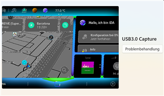
We are currently facing an issue with our video setup involving the Westar board. When using a single input, we are able to display the video, but the resolution quality is noticeably low.

However, when we connect both inputs—since we require higher image quality—the image disappears completely.

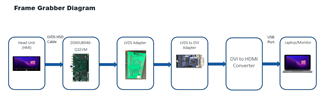
Here are the key details of our current setup:

  • Video Source: HMI of a vehicle
  • Resolution and Frequency: 1920x1080 @ 60Hz
  • Monitor: Laptop screen used to visualize the video   (supports 1920x1080 @ 60Hz)

Could you please assist us in identifying the root cause and guide us on how to resolve this issue?

Thank you in advance for your support.

  • Hi Anis,

    Thank you for sharing this issue.

    Can you share some further details on this setup:

    • Block diagram (serializer, color-resolution, etc.)
    • Is failure consistent across multiple devices and cables?
    • Have you tried patgen from deserializer and seen stable video output?

    Thanks,

    Ragav Subramanian

  •     

    Hello Ragav,

    Thank you for your quick response.

    Please find attached the Frame Grabber diagram.

    Regarding the PatGen, we are using the default settings. However, please note that we are unable to apply changes when attempting to set the timing source to internal.

    As for the Mode-Sel0, we have tried changing the value from 5 to 1, but that did not work. We also tried setting it to 6, but the result remained the same.

    For Switch S3, could you please confirm whether the BISTC switch should be set to the High or Low position?

    Here are the observed results:

    • When BISTC is set to High, the pixel clock = 128 MHz

    • When BISTC is set to Low, the pixel clock = 49 MHz

    Could you please advise:

    1. What are the correct settings to be applied using the ALP tool?

    2. What is the required configuration for the S0 and S3 switches?

    Thank you in advance for your support.

    Best regards,
    Anis Arous

  • Hi Anis,

    Thank you for sharing the block diagram and additional information.

    We usually do not see low resolution fuzzy display issues. Patgen will allow us to deduce if the issue is from the deserializer or incoming video.

    Regarding the PatGen, we are using the default settings. However, please note that we are unable to apply changes when attempting to set the timing source to internal.
    What are the correct settings to be applied using the ALP tool?

    For PatGen, the procedure in ALP to correctly program the device is shown below:

    1. Go to PatGen register page 
      1. Nothing to do on this page but it MUST be accessed before the PatGen Tab
    2. Go to PatGen page
      1. set timing to 'Intenal'
      2. set the timings and PCLK on the right side of the window
      3. click Apply
      4. click 'Enable Gnerator'
        1. once this is enabled the settings will be grayed out and you cannot modify timings
    As for the Mode-Sel0, we have tried changing the value from 5 to 1, but that did not work. We also tried setting it to 6, but the result remained the same.
    What is the required configuration for the S0 and S3 switches?

    Mode_sel0 depends on your oLDI output - port configuration and bit mode configuration. The settings will get applied at POR but if you are using ALP to program the device - the ALP will override the pinstrap configuration with the value set in programming. Please ensure you are changing the correct mode_sel setting in the registers.

    For Switch S3, could you please confirm whether the BISTC switch should be set to the High or Low position?

    S3 controls the BIST and PDB settings:

    • S3.1 - L for normal video operation and High for BIST Enabled
    • S3.2 - H for internal Pclk
      • Use internal PCLK with 1/N divider to set specified PCLK
      • For further PCLK capabilities - use the SER PCLK as input with M/N divider capabilities for more PCLK precision
    • S3.3 - Setting to control PDB (should be High as PDB is a useful functionality unless customer wants it disabled)

    Please ensure to set the same configuration through registers via ALP as ALP programming will override the pinstrap configuration

    To further assist you, do you mind sharing some details:

    • Information on corresponding serializer
      • Part #
      • Single/dual-link
      • Rate at which FPD operating
      • Can you access I2C on Ser
    • Laptop display TCON specifications

    Thanks,

    Ragav Subramanian

  • Hello Ragav,

      • Serializer Part #:
        The serializer is integrated in the Vechile HMI unit. 

      • Link Type:
        The HMI uses Dual-Link FPD-Link III, connected to the DS90UH948-Q1 deserializer.

      • Operating Rate:
        The video signal from the VW HMI is 1920x1080 60Hz.

      • I2C Access on Serializer:
        No, we cannot access the I2C interface of the serializer.

      • Asus PB278QV Panel/TCON Details:

        Based on the official specs:

        • Resolution: 2560 × 1440 (WQHD) at up to 75 Hz 

        • Pixel Clock: Calculated at ~153 MHz for 2560×1440@75 Hz (typical WQHD timing)

      We’ve made some progress  the video signal is now stable with no shaking. However, the image quality is still not optimal, and some colors appear incorrect or missing (e.g., noticeable color fringing and loss of color accuracy).

      We’re using a HMI as the video source with 1920x1080 @ 60Hz, connected to the DS90UH948 Module deserializer and a Westar LVDS-to-DVI converter. 

      Could you advise on optimal settings for:

      • Pixel clock and output mode (Dual OLDI vs Dual SWAP)

      • Any recommended register adjustments to improve color accuracy

      Thank you for your support.

  • Hi Anis,

    I need more information to better support you:

    • What was the steps to improve the image from your previous post?
    • What is your color-resolution (bpp)
    • Does cable movement affect video output? - this would point to signal integrity issues

    Please try driving video with Patgen from Des first and ensure video display is appropriate and let me know status.

    Pixel clock and output mode (Dual OLDI vs Dual SWAP)

    This will depend on your system configuration. Dual SWAP will swap the Left and Right pixels from outputting on P0 vs P1. By default the device will output L on P0 and R on P1. With Dual Swap, the device will output R on P0 and L on P1.

    Any recommended register adjustments to improve color accuracy

    We have RGB LUTs to enable white balancing - this can help improve your color-resolution (assuming no other issues are causing color degradation)

    See section from datasheet below (additional programming example shown in datasheet):

    Thank you,

    Ragav Subramanian

  • Hi Ragav,

    Thank you for your response and support.

    Please find below the details you requested to help you better assess our setup and remaining issues:

    1. Steps taken to improve the image from the previous post:
      We removed the HDMI-to-USB adapter and connected the video signal directly to a monitor instead of capturing it on the laptop. This significantly improved the image quality and stability

    As suggested, we plan to drive video with PatGen via the DES first to verify the video display output.

    Could you please provide:

    • The step-by-step procedure to correctly drive video from PatGen via DES?

    • Any specific settings or configurations required in the ALP tool?

    Also, regarding the RGB LUTs for white balancing:

    • Could you please share how we can enable and configure these LUTs?

    • Is it possible to access or adjust them using ALP

    We appreciate your guidance and look forward to your instructions.

    Best regards,
    Anis Arous

  • Hi Anis,

    Steps taken to improve the image from the previous post:
    We removed the HDMI-to-USB adapter and connected the video signal directly to a monitor instead of capturing it on the laptop. This significantly improved the image quality and stability

    This may indicate we are still dealing with a signal integrity or cable mismatch issue.

    As suggested, we plan to drive video with PatGen via the DES first to verify the video display output.

    Could you please provide:

    • The step-by-step procedure to correctly drive video from PatGen via DES?

    • Any specific settings or configurations required in the ALP tool?

    These steps are listed in my response earlier quoted below:

    For PatGen, the procedure in ALP to correctly program the device is shown below:

    1. Go to PatGen register page 
      1. Nothing to do on this page but it MUST be accessed before the PatGen Tab
    2. Go to PatGen page
      1. set timing to 'Intenal'
      2. set the timings and PCLK on the right side of the window
      3. click Apply
      4. click 'Enable Gnerator'
        1. once this is enabled the settings will be grayed out and you cannot modify timings

    You can use the scripting tab to perform the LUT configuration. 

    There is a sample script in Section 7.5.3.1 which you can copy directly to get started and modify with your LUT values.

    The sequence is as follows:

    1. Select corresponding RGB LUT in Register 0x2A[7:6]
    2. Write LUT values to addresses 0x00 - 0xFF
    3. Repeat steps 1-2 for R,G,B values
    4. Once all RGB LUT loaded, enable White Balance Register 0x2A[5]=1
      1. If you plan to dynamically change LUT(steps 1-3) after init, then set Reload Enable Register 0x2A[4]=1

    Thanks,

    Ragav Subramanian

  • Hello Ragav,

    The script was executed in section 7.5.3.1, but there was no change.

    We execute this script

    # Red: Keep linear
    board.WriteReg(0x2A, 0x70)
    for i in range(256):
        board.WriteReg(i, i)


    # Green: Slightly reduced (e.g. 90%)
    board.WriteReg(0x2A, 0xB0)
    for i in range(256):
        val = int(i * 0.9)
        board.WriteReg(i, min(val, 255))


    # Blue: Stronger reduction (e.g. 80%)
    board.WriteReg(0x2A, 0xF0)
    for i in range(256):
        val = int(i * 0.8)
        board.WriteReg(i, min(val, 255))


    # Enable WB and Reload
    board.WriteReg(0x2A, 0x30)

    As you can see, there is a color mismatch between the HMI image and our monitor image.

    Do you have any suggestions on how to fix this mismatch?

    Thanks in advance

    Arous Anis

  • Hi Anis,

    Since there is a large difference between both displays - I believe the root cause is a variation between both setups.

    Did the cable/signal integrity change between both setups? 

    If there is some additional loss with the display either in the LVDS to DVI adapter or DVI to HDMI.

    This connection could be degrading the video output signal quality which can result in color anomalies you are observing.

    Can you provide more details on the difference between the setups and try if you can simplify connection?

    Thanks,

    Ragav  Subramanian

  • Hello Ragav,

    Finally, we got this quality of image on the monitor and I think it's the best one.

    But we need to record the video on our laptop, and in this case, when we add an HDMI/USB adapter.

    The image's quality diminishes and it begins to flicker, have you any idea to fix this issue .

    we need to grape the video in the laptop.

    Thanks in advance,

    Best regards,

    Anis

  • Hi Anis,

    That video looks much better than the earlier images you shared. Glad we found the root cause.

    Based on this setup below, is the HDMI to USB adapter after the DVI-HDMI converter?


    For stable video with your application, we will need to reduce the loss from the 948 Des to display(laptop).

    To improve the signal integrity, we will need to reduce number of adapters or use higher-end adapters with a lower loss profile.

    A few questions:

    • Is there any optimization we can make in the chain of adapters?
      • Perhaps DVI to USB adapter (eliminating HDMI)
    • What video inputs does the laptop accept?

    Thanks,

    Ragav Subramanian