This thread has been locked.

If you have a related question, please click the "Ask a related question" button in the top right corner. The newly created question will be automatically linked to this question.

TUSB320LAI: TUSB320LAI CSR Register configuration by I2C Protocol

Part Number: TUSB320LAI
Other Parts Discussed in Thread: TUSB320

Tool/software:

Dear Texas Instruments  Support,


I am working on a project where I need to configure the TUSB320LAI (USB Type-C Configuration Channel Logic and Port Control) using a PIC16F1508 microcontroller over I2C using protocol.

I am using this IC with following PIN configuration from Hardware side,

  • PORT - NC – DRP mode
  • ADDR – PullUp - I2C is enabled and I2C 7-bit address is 0x67


Our Application (Requirement):

                USB Type-C connector which CC1 & CC2 PIN is connected to TUSB320LAI IC, will be working as host and connected to Any Cell Phone (like Android, iPad etc.) or Any system (like Mac book, Windows etc.). Whenever host (Any battery-operated device like iPad, Mobiles etc.) is connected that time host’s battery will be charge by board supply by using TUSB320LAI IC with up to 1 Amp, because of We need to keep host alive. And also, host will transfer data to connected device.

As per our above requirement, I am attempting to manually write configuration CSR registers, but I am encountering unexpected behaviour during testing. The IC does not behave accordingly


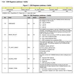
Test Case 1: – Behaviour of CSR Register 0x08:
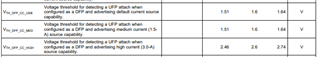
                According to the datasheet, the default value of register 0x08 of 7 & 6 bit is 00 (500 mA / 900 mA initial value at startup). However, when I write this register’s 7 & 6 bit is 01 (Mid 1.5 A), then after connecting any battery-operated device (like iPad, Mobiles etc.) to host USB Type-C connector, this device’s battery will not take any current from board.


Request:
Please suggest if required to any other CSR register of TUSB320LAI to achieve our requirement and also provide an example of how to configure the TUSB320LAI via I2C using a microcontroller. Also suggest any changes to our current hardware configuration.

Here is attachment of my code and our schematic of TUSB320LAI IC. Please find it.


Thanks for your support,
Best regards,

Mayank MirajkarTI_QUEERY.rar


TI_QUEERY.rar

  • Hi Mayank,

    In this configuration, what is the TUSB320 configuring as, A DFP or a UFP? You can double check by monitoring bits 7:6 of register 0x09.

    If the TUSB320 is configuring as a DFP, can you ensure that the ID pin is pulling down to 0V, and is connected properly to a VBUS switch or a GPIO on the SOC? The ID pin should be controlling when VBUS is sent.

    And just to confirm, when connecting to a mobile device, do you want your board to act as a DFP or a UFP?

    Is it possible to monitor the CC lines to confirm that the correct voltage and a connection is seen over the lines?

    Thanks,

    Ryan

  • Dear Texas Instruments Support,


    I made changes to the MCU code for I2C communication with the TUSB320LAI. After updating the code, we tested the following points based on your suggestions.


        Check ATTACHED_STATE register
    (7:6 Bit of 0x09 CSR Registers)
    ID Pin
    Status
    (Voltage)
    CC1
    Status
    (Voltage)
    CC2
    Status
    (Voltage)
    Charging Status of device
    which is attached on
    (USB Type-C) host port
    Data Transmition Status of device
    which is attached on
    (USB Type-C) host port
    Cell Phone
    (Android Phone)
    Dettached 00 - Not Attached 3.3 V 0.3 V
    (Pulse Mode)
    0.3 V
    (Pulse Mode)
       
    Attached 01 - DFP 0 V 0.934 V 0.015 V Done NA
    Cell Phone
    (iPad)
    Dettached 00 - Not Attached 3.3 V 0.3 V
    (Pulse Mode)
    0.3 V
    (Pulse Mode)
       
    Attached 01 - DFP 0 V 0.934 V 0.015 V Done NA
    Laptop Dettached 00 - Not Attached 3.3 V 0.3 V
    (Pulse Mode)
    0.3 V
    (Pulse Mode)
       
    Attached 10 - UFP 3.3 V 0.871 V 0.040 V NA Done

    We encountered an issue where the iPad starts charging when connected to the USB host port, but data transmission has now stopped. Previously, the iPad was transmitting data correctly, but charging was not working. The issue seems to have reversed.

    Please review the attached files and provide your suggestions accordingly.

    Your support would be greatly appreciated.


    Thanks for your support,
    Best regards,
    Mayank Mirajkar

    New Code.zip

  • Hi Mayank,

    Looking at the data you sent over, from what I can tell it doesn't look like the voltage on the CC lines is what we would expect for an active DFP connection:

    For a DFP connection. we would expect the voltage on the CC line to be a bit higher than that, especially considering if you are using higher CURRENT_MODE settings.

    Does adjusting the advertised current change the voltage on the CC lines when set as a DFP?

    Also, could you possibly provide a block diagram of your setup so I can better understand what your system looks like? A register dump may be good as well.

    On the schematic, I noticed there are multiple ports that use type-C connectors. Which port on the schematic is the TUSB320 meant to be attached to? Are the other connectors just meant to be pulled-up for a DFP configuration?

    Thanks,

    Ryan

  • Dear Ryan Sir,

    As per your mail,

    Your question: Does adjusting the advertised current change the voltage on the CC lines when set as a DFP?
    Our Answer: I have only set 0x08 CSR register 7:6 bit to 01 (CURRENT_MODE_ADVERTISE to Mid (1.5 A)), we have not any change the voltage on the CC line.

    Please Noted, I sent CC1 & CC2 Voltage in last sent Testing table, that was with respect to GND.

     We connect host to J7 Type-C pin connector, Another J6 & J8 Type-C pin connector working as device. Please Noted, Above testing table was tested with host (J7 Type-C pin connector).

    Our requirement is

    • When I connect any cell phone (iPad or Android phone) to host (J7 Type-C pin connector) TUSB320 IC will charge to host and also transfer data to device (J6 & J8 Type-C pin connector).
    • When I connect any System (Mac book or Windows PC or laptop) to host (J7 Type-C pin connector) TUSB320 IC will not charge to host and also transfer data to device (J6 & J8 Type-C pin connector).

    I face problem after configuration TUSB320 IC with given code, When I connected iPad to host, only host is charging not transfer any data to device.

    Please review the attached block diagram and provide your suggestions accordingly to TUSB320 IC configuration and also hardware modification if needed. Your support would be appreciated.


    Thanks for your support,
    Best regards,
    Mayank Mirajkar

    2352.Block Diagram.pdf

  • Hi Mayank,

    So you want TUSB320/U17 to connect to J7 and act as a DRP, configuring as a DFP when connected to a phone or iPad and providing power to the phone or iPad while being able to transfer data, and configuring as a UFP when connecting to a notebook, not providing power while still being able to transfer data?

    The question of whether this is possible or not heavily depends on whether the devices J7 will connect to are also set as DRP, or if they have a set role or not. If both devices connecting to J7 are set as DRP, there is no way to guarantee what role the TUSB320 will configure as. You can bias the TUSB320 to a certain role via I2C via the SOURCE_PREF bit however:

    It looks like currently, going by your table, the role you want is being set correctly, however, the ability to charge while transferring data is being hindered, correct? Is there anyway you can confirm from the host controller/SOC that an active USB connection has been made? The TUSB320 should not affect whether data transfer is possible, it should only set the ports role, and establish the connection as needed over USB-C

    I have only set 0x08 CSR register 7:6 bit to 01 (CURRENT_MODE_ADVERTISE to Mid (1.5 A)), we have not any change the voltage on the CC line.

    I am asking you to adjust this register just to confirm that when a different amount of current is pulled, the voltage level of the CC line changes accordingly. Are you saying that changing this to default is not changing the voltage on the line when connected either? When there is an active connection over the CC lines, I believe we should be seeing a higher voltage on the CC lines, per the datasheet: 

    :

    I believe the code should be fine, but I will review it, just in case.

    Thanks,

    Ryan

  • So you want TUSB320/U17 to connect to J7 and act as a DRP, configuring as a DFP when connected to a phone or iPad and providing power to the phone or iPad while being able to transfer data, and configuring as a UFP when connecting to a notebook, not providing power while still being able to transfer data?

    Yes, Correct.

    You can bias the TUSB320 to a certain role via I2C via the SOURCE_PREF bit however:

    Our Experiment,
    - When Set SOURCE_PREF bit as 11 – DRP will perform Try.SRC, TUSB320 IC will mostly try to charge to host/ J7 Type-C connector (host is like iPad or Laptop).

    - When Set SOURCE_PREF bit as 00 – Standard DRP (default), if host is iPad then TUSB320 IC will try to charge host/ J7 Type-C connector, and if host is PC or Laptop, then TUSB320 IC will consider as UFP mode . 

    It looks like currently, going by your table, the role you want is being set correctly, however, the ability to charge while transferring data is being hindered, correct?

        Yes Correct.

    Is there anyway you can confirm from the host controller/SOC that an active USB connection has been made?

       We can detect host connection by VBUS available voltage. ID pin of TUSB320 control VBUS_EN and VBUS_EN control VBUS, you can see in schematic which already sent you.

    Our Experiment,

    I use Host as - iPad mini-2, Convertor-Lightning to USB 3 Camera Adapter
    - When I connect USB 3 to USB type-C cable, connect host to my PCB board, TUSB320 IC will consider as UFP and host will not charge but connect to device Type-C connecter and transfer data.   

    - When I connect Lightning to USB type-C cable, connect host to my PCB board, TUSB320 IC will consider as DFP and host will charge and not transfer data.

    Our Requirement is at same time both Charging and data transfer is possible with host by use of TUSB320 IC?

    I attached all this experiment photos, please check it.

    /cfs-file/__key/communityserver-discussions-components-files/138/Experiment_5F00_Photoes.zip

    Experiment_Photoes.zip

    When there is an active connection over the CC lines, I believe we should be seeing a higher voltage on the CC lines, per the datasheet

      Does the CC line voltage have any impact on the data transfer functionality of the TUSB320 IC?

  • Hi Mayank,

    Our Experiment,
    - When Set SOURCE_PREF bit as 11 – DRP will perform Try.SRC, TUSB320 IC will mostly try to charge to host/ J7 Type-C connector (host is like iPad or Laptop).

    - When Set SOURCE_PREF bit as 00 – Standard DRP (default), if host is iPad then TUSB320 IC will try to charge host/ J7 Type-C connector, and if host is PC or Laptop, then TUSB320 IC will consider as UFP mode . 

    So when Try.SRC is used, does the TUSB320 configure as a DFP for both the iPad and the Laptop, or just the iPad?

    I use Host as - iPad mini-2, Convertor-Lightning to USB 3 Camera Adapter
    - When I connect USB 3 to USB type-C cable, connect host to my PCB board, TUSB320 IC will consider as UFP and host will not charge but connect to device Type-C connecter and transfer data.   

    This makes sense to me. If the TUSB320 is configuring as a UFP, it would be expecting the iPad to charge the device it's on, but would be able to allow the iPad to transfer files back and forth, as the iPad see's your board as a device, like a flash drive. The question of whether the iPad provides charging functionality or not is something our TUSB320 does not determine. If the TUSB320 were to charge the iPad, it would first need to be configured as a DFP.

    When I connect Lightning to USB type-C cable, connect host to my PCB board, TUSB320 IC will consider as DFP and host will charge and not transfer data.

    The TUSB320 is only in charge of completing the type-C connection via the CC pins, as well as advertising the max allowed current for charging. It is not in charge of establishing a USB3 connection or whether it can charge and transfer data or not. That's something that I believe is typically communicated over the USB lines. 

    Does the CC line voltage have any impact on the data transfer functionality of the TUSB320 IC?

    CC line voltage does not impact data transfer, however it can be used to judge whether there is a valid type-C connection or not, depending on if the voltage as at an acceptable voltage, or something is potentially externally affecting the voltage.

    Thanks,

    Ryan

  • Dear Ryan Sir,

    Thanks for quick response and share valuable information.

    As per your mail,

    The TUSB320 is only in charge of completing the type-C connection via the CC pins, as well as advertising the max allowed current for charging. It is not in charge of establishing a USB3 connection or whether it can charge and transfer data or not
    CC line voltage does not impact data transfer

    One of my team members from the hardware team reached out to TI Support regarding the selection and configuration of the TUSB320 IC about four months ago. Please refer to the following link,

    https://e2e.ti.com/support/interface-group/interface/f/interface-forum/1475854/tusb321-validating-concept-of-host-charging-using-configuration-channel-logic-and-port-control-with-vcon

    According to their response, "the TUSB320 IC can charge a device while supporting USB data transfer to and from the USB host without the need for a PD controller."

    However, based on our recent discussions and experimental results, it appears that the TUSB320 IC does not play a role in USB data transfer. Is that correct?

    Our requirement is to enable simultaneous charging and data transfer through the same USB Type-C port (host side).
    Currently, this requirement is not being fulfilled—only charging occurs when a host device (e.g., iPad or any Cell phone) is connected to the USB Type-C port using the TUSB320 IC.

    Could you please advise on a proper solution for achieving both charging and data transfer?

    • Are any hardware modifications required?
    • Is a PD (Power Delivery) controller necessary in this case?
    • Is it essential to use an IC that supports DRD (Dual Role Data)?
    • Can we achieve simultaneous iPad charging and data transfer using only the USB2534 and TUSB320 ICs?


    Thanks for your support,
    Best regards,
    Mayank Mirajkar

  • Hi Mayank,

    I will double check this and get back to you. From my understand, yes, something with role swap like a PD controller is needed if you wanted to do something like charge an iPad while allowing it to act as a host in a connection, as this would entail role swap support.

    However, based on our recent discussions and experimental results, it appears that the TUSB320 IC does not play a role in USB data transfer. Is that correct?

    Correct, the TUSB320 does not have any affect on data transfer. It just advertises or detects the max current allowed for charging. Though, from my understanding, that shouldn't stop a USB3 connection from being able to both charge a device and transfer data when set at the DFP. Not being able to transfer data at all would mean that both USB3 and USB2 connections may not be functional. Is there anyway you can confirm whether USB2 or 3 are working, I.E monitor the DP/DM lanes for USB2?

    Thanks,

    Ryan

  • Dear Ryan Sir,

    Thank you for your prompt response and for sharing valuable insights.


    Is there anyway you can confirm whether USB2 or 3 are working, I.E monitor the DP/DM lanes for USB2?

    Yes, USB 2.0/3.0 communication is functioning. Please refer to the test table below for our observations on the DP/DM lines:

    Deviece
    Name
    By Connected
    to PCB board 
    Condition Upstrim/Host  Port -J7
    Type-C Connector
    Host
    Charging
    Host
    Data Tranfer
    DM DP 
    No Deviece     0 V 0 V    
    iPad
    Connected
    with
    Lightning to Type-C cable  
      0 V 3 V dc Working Not Working
    with Converter,
    USB A to Type-C cable  
    Just Attached 0 V 3 V Pulse
    with 700 msec
    Not Working Working
    Just detached 0 V 1 V Pulse
    with 700 msec
    Continues
    Connected
    Very with Audio File
    play by Host application
    Laptop
    Connected
    with
    USB A to Type-C cable  
    Just Attached 0 V 3 V Pulse
    with 700 msec
     Not Working Working
    Just detached 0 V 1 V Pulse
    with 700 msec
    Continues
    Connected
    Very with Audio File
    play by Host application


    As I have mentioned previously, our core requirement is:
    “To enable simultaneous charging and data transfer through the same USB Type-C port (host side).”

    Despite several rounds of testing and experimentation, we have not yet achieved the expected results.

    We are preparing to submit the prototype to our customer next week, so we kindly request your urgent support in resolving this issue. Your guidance is crucial at this stage.

    We would greatly appreciate any suggestions on:

    • Whether any hardware modifications are needed (e.g., adding an additional IC)?
    • Any specific configuration required for the TUSB320?
    • Whether another IC such as a PD controller or DRD-capable IC is necessary to fulfil our use case?

    Additionally, if possible, we would be grateful if you could connect us with a TI engineer who specializes in this area and can help us meet this core requirement.

    Thank you again for your continued support.


    Thanks for your support,
    Best regards,
    Mayank Mirajkar


  • Hi Mayank,

    I think from the TUSB320 side of things, there's not much that can be done. The device should be setup as expected going by the hardware side of things. Only other things I can think of try that could possibly do something is disabling UFP accessory support via I2C, but even then I'm not sure that will solve all your issues.

    Additionally, if possible, we would be grateful if you could connect us with a TI engineer who specializes in this area and can help us meet this core requirement.

    For this, my best suggestion would be to submit an E2E to the PI team via one of their PD controllers, and asking them for their input and seeing if they believe a PD controller should be necessary for this system or not. Again, from the TUSB320 side of things, I'm not sure there's much else from our device we can do.

    Thanks,

    Ryan