


Part Number: TMUXHS4412
Tool/software:
In reply to my first question,
I am attaching the images I was able to capture of the LVDS signal using the oscilloscope. The image at the bottom shows the LVDS signal with 0.22µF capacitors in series on the line. The voltage levels seem to be well below the maximum limit, so this channel is working well.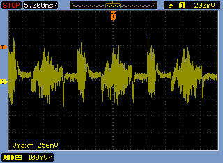
However, we found that the other channel is not actually an LVDS signal, but rather resembles a sinusoidal signal with a maximum voltage of 3V, which seems to exceed the IC’s maximum limits, likely causing the ICs to burn out.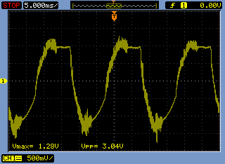
What other solution is there to prevent this signal from damaging the ICs? Is there any Texas Instruments IC similar to the TMUXHS4412 with higher voltage tolerance so that it doesn’t get damaged by this signal? It needs to be a switch LVDS, of course.
Additionally, one of our clients doesn't need the second signal to be switched — it can remain directly connected to the specific output — so we decided to bypass the IC for the second signal and connected the input directly to the output. However, in some test devices, some ICs are still being damaged by the LVDS signal. The purpose of these devices is to test other end-of-line LVDS equipment, so we suspect that some faulty devices may be sending a bad LVDS signal and damaging the ICs again. What other solution is available to absorb LVDS spikes? Would placing two 1.8V Zener diodes on the lines help avoid overvoltage? Or would that distort the signal too much? Do you have any IC similar to the HS4412 that is more robust? Or another IC in line to absorb the signal?
Best Regards!
