DS90UB941AS-Q1: Joynext 941 Flashing Screen

Part Number: DS90UB941AS-Q1
Other Parts Discussed in Thread: LMK3H0102

Tool/software:

Joynext has report 2 new flash- screen case of 941AS which they have reported before. 1 pcs from  After-sales Field  and the other from VW assembly plants. The 2 pcs of  flash- screen Head-units returned to JNN in last June.

On the condition of  flash- screen phenomena reproducing, they tried the actions below:

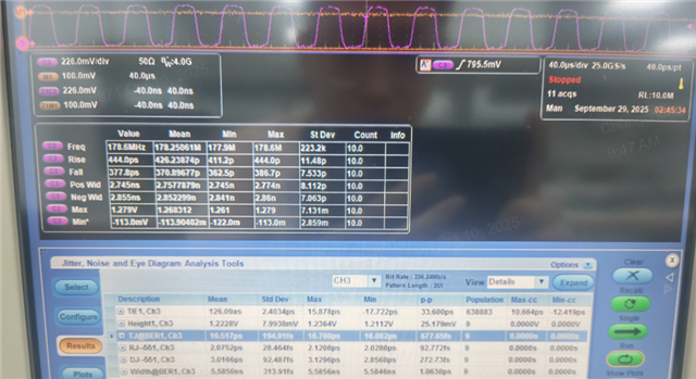
  1. 3rd party company measures and records the pictures and signals of each frame that SOC outputs with the tool  signal analyzer, report as attached: 01-d0.pdf
  2. There is  no DSI error  on the device of  signal analyzer  and  no flash-screen issue when playing back the pictures recorded by signal analyzer ;

So they concluded that there is no errors with the SOC outputting signals.

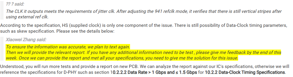
Base on above, they insist on the failure was caused by 941, and request TI to continue to assist in the next step analysis:

Measure the following four types of  PCBAs with signal analyzer to check whether the DSI error occurs;

  • 1 piece of OK PCBA that does not flash screen , 1 piece of flashing  screen PCBA, 2  piece of  PCBA ---done the test of AB between two PCBAs ;
  • Testing Environment construction: 1pcs of  wiring harness, test screen, CAN line(it could be removed )

Can you please help support on this case to help them find the root cause of the flash- screen? And provide express receiver and address information to get the new returned ECU with 941

BU analysis results before:

Joyson DS90UB941AS-Q1 flashing screen issue accelerate Dec 16.pdf

Joyson - DS90UB941AS-Q1 Flickering Screen Analysis and Root Cause Theory.pdf

Best Regards,

Xiaowei Zhang

  • Hi Xiaowei,

    Can you confirm if this issue is on the updated PCBA with TI suggestions implemented or the original PCBA that was already root caused?

    TI will not be proceeding forward with any additional testing on the PCBA at this time as outlined in previous correspondence. This is system-level testing, which, as discussed previously, will have to be the customer’s responsibility going forward. TI already has completed sufficient system-level testing on behalf of the customer as a courtesy. From this testing, sufficient conclusions were drawn regarding the impact of the capacitance on the DSI traces (as highlighted in the root cause slides shared on December 16). If additional global timing parameters testing of the DSI TX of the particular SoC on the board, you will have to acquire your own equipment and/or work with a third party to conduct these tests in parallel to any IC-level tests being conducted here in Santa Clara.

    The first test can be conducted because it is IC-level testing since we will be testing with our own silicon validation board.

    The second test, however, is system-level testing, which as aligned in previous correspondence will have to be the customer’s responsibility going forward. TI already has completed sufficient system-level testing on behalf of the customer that was sufficient for conclusions to be drawn regarding to the impact of the capacitance on the DSI traces (as highlighted in the root cause slides shared on December 16). We will not be fulfilling this secondary request.

    TI has already gone the extra mile to complete all system-level validation to date for the customer. Typically, this is the customer’s responsibility as this goes beyond the TI device-level. Going forward, if any additional testing is desired, this will have to be completed by the customer directly.

    Thanks,

    Ragav Subramanian

  • Hi Ragav,

    From cuurent test results from 3rd party, the DSI input signal are all good,so customer don't believe it's caused by their weak design,and insist on 941 IC have quality issue.

    Can you please help support a meeting with customer to highlight the root cause and provide some suggestiins for their forward test?

    Best Regards,

    Xiaowei Zhang

  • Hi Xiaowei,

    We need more information to understand the situation before meeting with the customer.

    Is this issue occurring on the updated board? And are these test results for the original or updated board?

    Thanks,

    Ragav Subramanian

  • Hi Ragav,

    The issue and test results occurs on the updated board, customer feedback they didn't receive the original board returned from TI.

    Best Regards,

    Xiaowei Zhang

  • Hi Xiaowei,

    What is the failure rate on the updated board compared to original board?

    Can you provide updated board layout files? (altium preferred)

    Thanks,

    Ragav Subramanian

  • Hi Ragav,

    I think you may have misunderstood, Joynext didn't change their layout. What I mean is they operate the test on the new reported issue ECU rather than the original board shipped to TI. The new reported issue ECU didn't show timing error, that's why Joynext don't agree with the analysis you provide before. 

    Best Regards,

    Xiaowei Zhang

  • Hi Ragav,

    About the config you provided, Joynext test it with 1 new report issue ECU and the issue shipped to BU before.

    When test with new reported issue ECU, only vertical lines observed, no flicker issue observed even after letting system run for long time.

    When test with issue ECU shipped to TI before, only vertical lines observed at the beginning, flicker issue observed after letting system run for long time.

    They asked:

    Why does this mode have an optimization effect on flashing devices compared to the previous mode?

    What other methods can be used to optimize the vertical lines issue?

    The specific modifications are as follows:

    1. Change the DSI output mode at the SOC side to non-burst_sync_ivent mode, and ensure it works through log printing.

    2. Config 941 register, please help check is it correct?

    • Set DSI_CONFIG_0 0x20[4] = 0. This informs the UB941 that it should only expect HSS/VSS packets and overrides for HSYNC and VSYNC
    • Set DSI_HSW_CFG_HI (0x30) and DSI_HSW_CFG_LO (0x31) based on video parameters
    • Set DSI_VSW_CFG_HI (0x32) and DSI_VSW_CFG_LO (0x33) based on video parameters

    About 4. SoC must be configured to convey accurate DPI-type timing for HSS and VSS packets for this particular mode

    Does it mean to confirm whether the HSS VSS data packet was sent from the DSI data packet? Currently, there is no way to confirm the data packet, but from my understand that changing the mode will definitely change this data packet. Then, the timing content can be confirmed as follows without any problem.

    Best Regards,

    Xiaowei Zhang

  • Hi Xiaowei,

    Thanks for sharing all this data.

    Why does this mode have an optimization effect on flashing devices compared to the previous mode?

    The Event mode programs the sync width into the device and does not rely on detecting sync HSE/VSE. The fact that this is improving performance indicates the device outputs more robust video with hard-coded sync widths and the DSI input most likely has more variation in sync widths from SOC due to either SOC behavior or system signal loss. In the pulse mode, the device is forced to rely on the HSS/HSE and VSS/VSE to detect sync widths and depending on the DSI input, this sync widths can have variation.

    What other methods can be used to optimize the vertical lines issue?

    Vertical lines usually occur as an issue at certain PCLKs. We would recommend operating at a different PCLK and see if problem goes away - however, that would not be acceptable to customer in this case. I will discuss with internal team what other actions can be taken. 

    1. Change the DSI output mode at the SOC side to non-burst_sync_ivent mode, and ensure it works through log printing.

    Correct

    Config 941 register, please help check is it correct?

    • Set DSI_CONFIG_0 0x20[4] = 0. This informs the UB941 that it should only expect HSS/VSS packets and overrides for HSYNC and VSYNC
    • Set DSI_HSW_CFG_HI (0x30) and DSI_HSW_CFG_LO (0x31) based on video parameters
    • Set DSI_VSW_CFG_HI (0x32) and DSI_VSW_CFG_LO (0x33) based on video parameters

    Correct

    About 4. SoC must be configured to convey accurate DPI-type timing for HSS and VSS packets for this particular mode

    Does it mean to confirm whether the HSS VSS data packet was sent from the DSI data packet? Currently, there is no way to confirm the data packet, but from my understand that changing the mode will definitely change this data packet. Then, the timing content can be confirmed as follows without any problem.

    Yes this means SOC must send HSS/VSS packets in the DSI protocol

    Thanks,

    Ragav Subramanian

  • Hi Ragav,

    What other methods can be used to optimize the vertical lines issue?

    Vertical lines usually occur as an issue at certain PCLKs. We would recommend operating at a different PCLK and see if problem goes away - however, that would not be acceptable to customer in this case. I will discuss with internal team what other actions can be taken. 

    Do you have more ideals to eliminate the vertical line issue? 

    Best Regards,

    Xiaowei Zhang

  • Hi Xiaowei,

    Do you have more ideals to eliminate the vertical line issue? 

    The best suggestion we have at the moment is to change the PCLK and see if vertical lines go away. Can you share T-CON specifications? There may be a tolerance on the PCLK, we can try to vary the PCLK within the tolerance and see if video improves.

    Thanks,

    Ragav Subramanian

  • Hi Ragav,

    T-CON spec as below:

    Can you share T-CON specifications? There may be a tolerance on the PCLK, we can try to vary the PCLK within the tolerance and see if video improves.

    Customer asked how can they test with this?

    Best Regards,

    Xiaowei Zhang

  • Hi Xiaowei,

    About 4. SoC must be configured to convey accurate DPI-type timing for HSS and VSS packets for this particular mode

    Does it mean to confirm whether the HSS VSS data packet was sent from the DSI data packet? Currently, there is no way to confirm the data packet, but from my understand that changing the mode will definitely change this data packet. Then, the timing content can be confirmed as follows without any problem.

    1) Try changing the DSI settings shown in your earlier message with both the min and max timing specifications of the T-CON - specifically by modifying the blanking parameters. These settings will then have to be modified on the 941as side as well.

    2) My second suggestion is to review the following E2E. The customer was experiencing issues with a certain color due to power requirements for a given color. Can you share an image of the vertical lines? It could potential be an issue where T-CON is having difficulty driving power for high-power pixel colors such as white. Are there certain images or colors that have the vertical lines issue and others that do not? 

     https://e2e.ti.com/support/interface-group/interface/f/interface-forum/1491061/ds90ub948-q1-displayed-picture-crashes-if-the-window-is-maximised-or-moved-over-the-edge

    Thanks,

    Ragav Subramanian

  • Hi Ragav,

    1) Try changing the DSI settings shown in your earlier message with both the min and max timing specifications of the T-CON - specifically by modifying the blanking parameters. These settings will then have to be modified on the 941as side as well.

    Customer are trying this. For the DSI mode sync_ivent + H slot screen parameter change +  941 HSW register modification, customer said they only see the following HSW configuration. Do other porch configurations need to be configured in this mode?
    0x30 DSI_HSW_CFG_HI
    0x31 DSI_HSW_CFG_LO

    2) My second suggestion is to review the following E2E. The customer was experiencing issues with a certain color due to power requirements for a given color. Can you share an image of the vertical lines? It could potential be an issue where T-CON is having difficulty driving power for high-power pixel colors such as white. Are there certain images or colors that have the vertical lines issue and others that do not? 

     https://e2e.ti.com/support/interface-group/interface/f/interface-forum/1491061/ds90ub948-q1-displayed-picture-crashes-if-the-window-is-maximised-or-moved-over-the-edge

    Customer feedback the pixel display of vertical line is not in the order of RGB, such as RGB being reversed or certain R, G, B not being displayed, and the position of vertical line will also change as display content change.

    Best Regards,

    Xiaowei Zhang

  • Hi Xiaowei,

    Customer are trying this. For the DSI mode sync_ivent + H slot screen parameter change +  941 HSW register modification, customer said they only see the following HSW configuration. Do other porch configurations need to be configured in this mode?
    0x30 DSI_HSW_CFG_HI
    0x31 DSI_HSW_CFG_LO

    Please configure the following:

    • 0x30-0x31 - DSI_HSW_CFG
    • 0x32-0x33 - DSI_VSW_CFG

    I would recommend ensuring EN_PCLK_DIV_OV=0 - this will ensure autodetection of PCLK and customer will not have to manually write PCLK for each change in video parameters.

    Please let me know update on testing and we will proceed forward from there (example test matrix shown below)

    Hsync Vsync
    Nominal Nominal
    High value Nominal
    Nominal High value
    High value High value
    Low value Nominal
    Nominal Low value
    Low Value Low Value

    Thank you,

    Ragav Subramanian

  • Hi Xiaowei,

    Please note I will be out of office till next Tuesday 8/5.

    Thank you,

    Ragav Subramanian

  • Hi Ragav,

    0x3A register EN_PCLK_DIV_OV bit is 0.

    Below are their test summary, seems different combination of hsync and vsync have no improvement on vertical line issue.

    Best Regards,

    Xiaowei Zhang

  • Hi Xiaowei, thank you for summarizing these tests results. 

    I am assuming "There is no screen displayed behind" means no backlight, please correct me if this is incorrect

    Hsync Vsync Result PCLK
    Nominal Nominal No flickering / Vertical Stripe 177.98 MHz
    High Nominal Flickering + No Screen 180.27 MHz
    Nominal High No flickering / Vertical Stripe 178.26 MHz
    High High Flickering + No Screen 180.55 MHz
    Low Nominal No Flickering / Vertical Stripe 177.67 MHz
    Nominal Low Flickering + No Screen 177.84 MHz
    Low Low N/A (I do not see this screenshot) N/A

    Two comments -

    First point

    Customer feedback the pixel display of vertical line is not in the order of RGB, such as RGB being reversed or certain R, G, B not being displayed, and the position of vertical line will also change as display content change.

    This agrees with Ragav's second point, where the phenomena will follow the content displayed on the screen (abnormality only occurs with certain content displayed):

    It could potential be an issue where T-CON is having difficulty driving power for high-power pixel colors such as white. Are there certain images or colors that have the vertical lines issue and others that do not? 

    (1) Is there a way to change the pattern to be fully one color to test if the vertical line issue only happens due to a specific sent image or color from the SoC? I know the issue will not occur with SER PATGEN.

    Second point

    The way the HS and VS were programmed may not match the anticipated TCON values for Low and High when using the HS, VS investigation. This may be why the flickering occurs even when the PCLK is within the TCON limitations. Here is my recommendation to try for all the cases requested by Ragav:

    When testing High Htotal values and Nominal Vtotal values, the following was used:

    However, the TCON specifies when using the max PCLK the H_Back-Porch should be reduced:

    So it should be

    .h_front_porch = 60,
    .h_back_porch = 10,
    .h_sync_width = 58,
    High Value
    
    .h_front_porch = 12,
    .h_back_porch = 44,
    .h_sync_width = 24,
    Low Value
    
    .v_front_porch = 10,
    .v_back_porch = 4,
    .v_sync_width = 4,
    High Value
    
    .v_front_porch = 4,
    .v_back_porch = 4,
    .v_sync_width = 1,
    Low Value

    (2) I have edited this for the rest of the configurations used, the sync widths should be correct for each case but please also make sure the SoC is sending the other correct parameters for front_porch and back_porch for the TCON.

    we can try to vary the PCLK within the tolerance and see if video improves.

    This should then satisfy this investigation.

    Let me know if you have any questions.

    Best,

    Miguel

  • Hi Miguel,

    I am assuming "There is no screen displayed behind" means no backlight, please correct me if this is incorrect

    No, it means backlight is good, but no display.

    (1) Is there a way to change the pattern to be fully one color to test if the vertical line issue only happens due to a specific sent image or color from the SoC? I know the issue will not occur with SER PATGEN.

    When test with fully one color pattern, no vertical line issue.

    Internal timing and internal clk, result is good
    Internal timing and external clk, result is good
    External timing and External clk , result is abnormal

    Below are latest test summary:

    Best Regards,

    Xiaowei Zhang

  • Hi Xiaowei,

    Thanks for testing these configurations as well as confirming the different clocking uses from the 941AS.

    When test with fully one color pattern, no vertical line issue.
    position of vertical line will also change as display content change

    Thanks for testing this from SoC output, can you try color bars or other patterns to double-confirm there is not one specific color combination that causes the loss of pixels?

    What we are trying to investigate here is the content change = position of the vertical line, it is assumed there is a specific pixel pattern or combination at the RX of the device that causes the phenomena at the display side.

    Internal timing and internal clk, result is good
    Internal timing and external clk, result is good
    External timing and External clk , result is abnormal

    Based on these tests and the timings used for each of the corrected cases, it appears that none of these configurations can achieve no flicker, is the nominal hblanking and nominal vblanking configuration still good?

    At this point, the next recommendation we can try to improve the PCLK of the input is to fine tune the register settings with nominal incoming video timings from the SoC.

    From the previous test, it appears that nominal / nominal combination has no flickering screen but still has the vertical lines.

    The suggestion is to increase/decrease the programmed DSI_HSW_CFG first by +/-1 px increments, then do the same with DSI_VSW_CFG but keeping the SoC output the same.

    • This test determines if the 941AS can fine-tune adjust the incoming PCLK to accommodate for the vertical line behavior.

    As a final check, the vertical line behavior follows ABA swap?

    Thanks for your support,

    Miguel

  • Hello Miguel:

    1.Using patgen test, the vertical stripes cannot be seen. The 0x64 register bit4-bit7 tried different patgen images, but no vertical stripes were seen.

    2.Adjust HSW +/- 1pixel to see the vertical stripes that change to "/" , "\" shapes.
    Adjust vsw to 1 and the screen is not displayed.

    3.In addition, adjusting the DSI working mode cannot completely solve the problem of splash screen. We also tried several other pieces to optimize the splash screen effect, but the splash screen will still occur over time.

    4.Yes, the vertical line and panel flick behavior follows ABA swap.

  • Hello,

    Thank you for the feedback.

    1.Using patgen test, the vertical stripes cannot be seen. The 0x64 register bit4-bit7 tried different patgen images, but no vertical stripes were seen.

    Can you please try this PATGEN test from the SoC? I still am interested to know how a gradient pattern and color bars would react when received at the RX of the 941AS, to determine the dependency on pixel pattern / color. 

    • This is the SER pattern, which we know will not have any issues

    Since the HSW adjust changes the shape of the stripes, I think that the nominal value should be used only with non-burst sync event mode. 

    At this point we have tried several different software configurations to improve the RX CLK of the device, since the issues still occur have there been any hardware attempts to optimize the screen abnormality?

    Best,

    Miguel

  • Hi Miguel,

    About the signal and timing mismatch error you mentioned before. Customer asked if specific data could be provided, such as the signal and timing mismatch, what's the tolerance is acceptable? Customer want to use these data to challenge Qualcomm their DSI output can't meet 941A requirement.

    Best Regards,

    Xiaowei Zhang

  • Hi Xiaowei,

    These are the 941AS datasheet specifications from the DSI data and clock perspective of the 941AS device. 

    Additionally I want to add the DSI receiver specifications given from both MIPI and FPD-Link

    From 941AS datasheet

    From MIPI D-PHY Specification

    You may also reference from the MIPI D-PHY that all jitter specifications are under 100-Ohms differential termination.

    Please let me know if you have any additional questions!

    Best,

    Miguel

  • Hello Miguel:

    我们内部确认,当前只有jitter这个不满足要求,但是针对这个问题case,验证下来与external timing和941之间有关联,当使用外部时钟芯片,不使用DSI时钟时,在满足clk jitter值要求的时候,问题941还是存在竖条纹的问题,对此,您还有什么看法?

    We internally confirm that only jitter does not meet the requirements at present, but for this problem case, it is verified that it is related to external timing and 941. When using an external clock chip and not using a DSI clock, when the clk jitter value requirement is met, there is still a problem of vertical stripes in question 941. What do you think about this?

  • Hello,

    when the clk jitter value requirement is met, there is still a problem of vertical stripes in question 941. What do you think about this?

    I do believe that the issue of flickering and to some extent the vertical lines is related to the jitter specification. However, it seems the two issues are separate in their reproduction.

    One concern that is previously pointed out in the layout review involves the routing of the data trace D0 P/N, please see below.

    I think this is further supported by the following information:

    • Adding additional impedance to DSI D0 trace reduces flicker / stripe abnormality
    • Internal PATGEN of the 941AS (such as color bars) does not show the issue

    Please let me know if you have any further questions.

    Best,

    Miguel

  • Hello
    补充一下背景,我们将问题件941通过ABA交叉实验焊接在优化后的GP SOP4的PCBA板子上,竖条纹现象依然存在。
    这个SOP4 PCBA优化满足了之前描述的两个问题

    To add to the background, we welded the problem piece 941 onto the optimized GP SOP4 PCBA board through ABA cross-experiment, and the vertical stripe phenomenon still exists.
    This SOP4 PCBA optimization meets the two problems described previously. Differential Impedance Routing and Layer Stack Up questions have been solved.

    我们在GP SOP4 PCBA上也有外部时钟芯片LMK3H0102,它输出的CLK是满足jitter clk要求的,941调整使用external ref clk后验证显示还是存在竖条纹现象。

    您描述的使用941内部画面没问题, 是否只能说明941显示输出的画面没问题,但是941作为RX接收端,接收SOC的数据是否会有问题呢?

    We also have an external clock chip LMK3H0102 on the GP SOP4 PCBA. The CLK it outputs meets the requirements of jitter clk. After adjusting the 941 refclk mode, it verifies that there is still vertical stripes after using external ref clk.

    The internal PATGEN of the 941AS does not show the issue you described can only indicate that the 941 displays the output screen, but will there be any problems with the data book receiving the SOC as the RX receiver?

  • Hi Miguel,

    These are the 941AS datasheet specifications from the DSI data and clock perspective of the 941AS device. 

    Customer said they did not get the answer that they want. Below are their feedback to your answer:

    Regarding the background, we have finished the ABA testing between X40(after fixing the issue you pointed)and TI chip(issue happened.)
    The issue has been improved but not totally solved. Still find vertical stripe phenomenon.

    Need you side provide some analysis for this issue.

    Regarding the specification as you mentioned has been met in the current case:

    DSI data: 75MHz – 750MHz
    Clock perspective: 0.3
    Resistance: 80-125 Ω

    To ensure the information was accurate, we plan to text again.
    Then we will provide the relevant report. If you have any additional information need to be test , please give me feedback by the end of this week. Once we can provide the report and met all your specifications, you need to give me the solution for this issue.

    Thank you

    Best Regards,

    Xiaowei Zhang

  • Hi Xiaowei,

    Thanks for providing this update,

    We internally confirm that only jitter does not meet the requirements at present,

    I would like to know more about which jitter requirement is not met.

    ABA cross-experiment, and the vertical stripe phenomenon still exists.

    This supports the earlier suggestion that the issues of the vertical stripe and the flickering are separate reproductions from the old system, as there is no mention of flicker here. We can focus on the vertical stripe as a separate issue from here.

    Differential Impedance Routing and Layer Stack Up questions have been solved.

    How does the new layout compare to the old layout? I see there may have been this internal forum related to the layout review: E2E.

    Please correct me if this is the wrong layout - but have the feedback been implemented, especially in consideration to the DSI traces and GND planes?

    In the previous thread, it can be seen on the DSI register pages that when DSI page 0x21 = 0x61, DSI_ERR_COUNT (register 0x29) is 0x0 in the normal case and 0xFF in abnormal case. Is this still consistent with the new layout as well?

    The CLK it outputs meets the requirements of jitter clk. After adjusting the 941 refclk mode, it verifies that there is still vertical stripes after using external ref clk.

    According to the specification, HS (supplied clock) is only one component of the issue. There is still possibility of Data-Clock timing parameters, such as skew specification. Please see the details below:

    To ensure the information was accurate, we plan to text again.
    Then we will provide the relevant report. If you have any additional information need to be test , please give me feedback by the end of this week. Once we can provide the report and met all your specifications, you need to give me the solution for this issue.

    Understood, you will run more tests and provide a report on new PCB. We can analyze the report against our IC's specifications, otherwise we will reference the specifications for D-PHY such as section 10.2.2.2 Data Rate > 1 Gbps and ≤ 1.5 Gbps for 10.2.2 Data-Clock Timing Specifications.

    Some other last suggestions from the team to determine if there are any other issues with specific colors at the display include:

    • White balance at 948 to see if specific colors are causing vertical lines at the T-CON side.
    • Increase power for TCON to see if there is any issue covering specific color depths / bit intensities.
    • Testing different color patterns from SoC TX (Color bars, gradients) to see if there is an issue with receiving specific color combinations / pixel intensities.

    Please let me know if you would like more information about these tests, otherwise we can focus on specifications.

    Best,

    Miguel

  • Hello TI:

    Sorry to update later because holidays.

    如下是我们使用lmk3h0102芯片输出的时钟作为参考时钟给到941时测量的jitter值,这个值是符合spec要求的,但是问题竖条纹现象还是存在的,之前使用的soc dsi clock测量的jitter不符合spec.

    The following is the jitter value measured when we use the clock output by the lmk3h0102 chip as the reference clock to 941. This value meets the spec requirements, but the problem of vertical stripes still exists. The jitter measured by the soc dsi clock used before does not meet the spec.

    是的,我们可以先关注与当前的竖条纹问题,但是3块闪屏问题车机在放置一晚后依旧1台低概率出现闪屏。

    Yes, we can focus on the current vertical stripe problem first, but among the three pcs boards with flickering 941, one of them will still have a flickering screen with a low probability after being left for a night.

    是的,新板子优化了pcb走线与GND。

    Yes,the new board optimized the DSI traces and GND planes? 

    我将与硬件同事确认下新板子是否给过TI review.

    I will confirm with my hardware colleagues whether the new board has been reviewed by TI.

    新板子上闪屏问题件依然存在0x29寄存器值为0xFF,请问这个是否不会清除,只要发生过,下次芯片再上电不会被清除吗?

    The flash screen problem still exists on the new board. The 0x29 register value is 0xFF. Will this be cleared? As long as it has happened, will it not be cleared next time the chip is powered on?

    我们会用新板子去做DPHY测试,确认您说的几项

    We will use the new board to do DPHY testing to confirm the few things you mentioned.

    1.我们之前尝试过使用948打patgen,并没有出现过竖条纹等异常

    We have tried using 948 to apply patgen before, and there were no abnormalities such as vertical stripes.

    2.增加TCON power目前不太好实现,我们也用一供和二供屏分别尝试过,都存在竖条纹现象,因此确认与TCON屏端无关联。不知您是否认可。

     Increasing TCON power is currently not easy to implement. We have also tried it with the first and second supply screens, and there are vertical stripes in both cases, so it is confirmed that it is not related to the TCON screen side. I don't know if you agree.

    3.SOC端输出不同的color bars我理解肯定存在竖条纹,目前还没有时间验证,不过之前分析灰色画面竖条纹最明显。

    The SOC terminal outputs different color bars. I understand that there must be vertical stripes. I haven’t had time to verify it yet. However, the vertical stripes on the gray screen are the most obvious after previous analysis.

    我们还想知道当clk jitter要求满足时,dphy测试也满足时,如果还有竖条纹,且排除了TCON端的问题,那是不是只有941芯片有问题呢?

    We also want to know that when the clk jitter requirements are met and the dphy test is also met, if there are still vertical stripes and the problem on the TCON end is eliminated, is it only the 941 chip that has the problem?

  • Hello,

    Sorry to update later because holidays.

    No worries, thank you for the update.

    The following is the jitter value measured when we use the clock output by the lmk3h0102 chip as the reference clock to 941. This value meets the spec requirements, but the problem of vertical stripes still exists. The jitter measured by the soc dsi clock used before does not meet the spec.

    Understood, is the SoC DSI clock outside of specifications in general or only on the previous layout?

    • Does the jitter specification meet on the new layout from the SoC?

    Additionally, the LMK3H0102 chip may provide a clean reference for the DSI CLK, but the DSI data lane may still be affected by the routing concerns that were previously mentioned from the layout. The data lane 0 may still have bit errors received at the data input in this case, which may induce the vertical stripe.

    • Has flickering been observed using LMK3H0102 reference clock?
    Yes, we can focus on the current vertical stripe problem first, but among the three pcs boards with flickering 941, one of them will still have a flickering screen with a low probability after being left for a night.

    I understand, the flickering may be more severe issue to handle but I believe they are symptoms of the same phenomena.

    是的,新板子优化了pcb走线与GND。

    Yes,the new board optimized the DSI traces and GND planes? 

    我将与硬件同事确认下新板子是否给过TI review.

    I will confirm with my hardware colleagues whether the new board has been reviewed by TI.

    我们会用新板子去做DPHY测试,确认您说的几项

    We will use the new board to do DPHY testing to confirm the few things you mentioned.

    Understood, thank you. Please keep us updated with findings.

    新板子上闪屏问题件依然存在0x29寄存器值为0xFF,请问这个是否不会清除,只要发生过,下次芯片再上电不会被清除吗?

    The flash screen problem still exists on the new board. The 0x29 register value is 0xFF. Will this be cleared? As long as it has happened, will it not be cleared next time the chip is powered on?

    The DSI_ERR_COUNT (register 0x29) is reported and cleared on read.

    For accurate reading, the error counter can be disabled by clearing CFG registers 0x22 and 0x23 prior to reading the value on register 0x29.

    ==--==--==--==--==--==--==--==--==--==--==--==--==

    I think the current status of the debug depends on the analysis of the old board and new board, and whether all the recommendations and feedback have been implemented from the last layout review from the internal thread.

    1. In the old PCB design, adding additional capacitance to the D0 data trace resolved flickering and sometimes vertical line issues, is this behavior consistent with the phenomenon seen on the new PCB designs?
    2. Let us investigate the feedback implementation on the new PCB design, to make sure the points of interest were resolved.
    3. Please continue to test PATGEN from the SoC terminal, to determine if a specific color pattern (such as grey gradient) is able to reliably reproduce the vertical stripes.

    Please let us know analysis feedback from the new layout as soon as possible. Thank you for the tests and organized information.

    Best,

    Miguel

  • Hello Miguel:

    We tested the board in question according to MIPI DPHY, and the test items all met the requirements.

    Please check whether the test report I uploaded meets the spec requirements of DS90UB941.

    T_setup-hold.zipXW0758_MIPI D-phy.pdf