This thread has been locked.

If you have a related question, please click the "Ask a related question" button in the top right corner. The newly created question will be automatically linked to this question.

DP83822I: LAN cable connection before the PHY power up. (Stress from link partner NLP/FLP undershoots)

Guru 19785 points
Part Number: DP83822I

Tool/software:

Hello,

I would like to ask a general question about Ethernet PHY use case.

Generally, desktop computers are turned off without unplugging the LAN cable. (Link partner : Router/Switching HUB is powered up, but, the computer itself using the PHY is power off.)

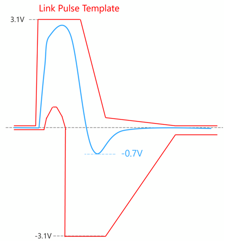
In this situation, Ethernet PHY in this computer continuously receive NLP/FLP which could have undershoot below the Absolute Maximum Rating described in the datasheet.

Undershoot may depend on board design, however, I can find some waveform which is exceeding -0.5V in E2E. 

Since the device is receiving the voltage which exceeds the Absolute Maximum Rating, I am thinking that the device could be damaged.

<Question1>

Is TI device designed to withstand such use case ? 

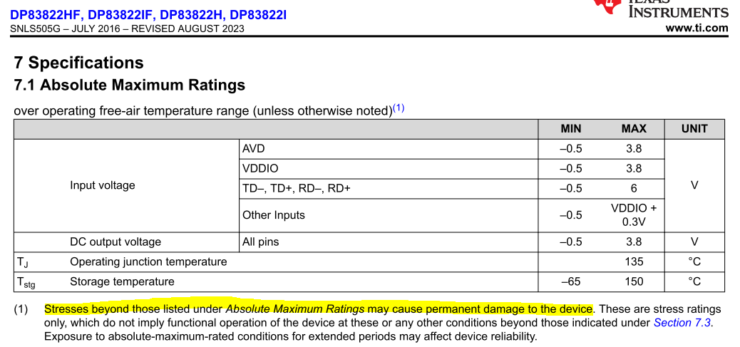
Most of the device seems to have Absolute Maximum Rating MIN as -0.3V or -0.5V for MDI pins.

<Question2>

Is it not recommended to connect the LAN cable before the system (PHY) power up ? 

Best Regards,

Kawai

  • Kawai-san

    The PHY is connected through an external discrete or integrated transformer. That transformer provides several feature such as

    • Impedance Matching: Transformers match the impedance of the Ethernet cable to the network interface, minimizing signal reflections that can lead to distortion and potentially cause overshoot and undershoot.
    • Signal Isolation: They electrically isolate the Ethernet device from the network, preventing issues like ground loops and common-mode noise, which can degrade signal quality and contribute to signal integrity problems.
    • Common Mode Rejection: Transformers effectively reject common-mode signals, which can attenuate common-mode signals picked up by the cable from the environment, improving the signal-to-noise ratio. This helps the PHY chip more easily recover the data signal and reduces the likelihood of signal degradation, which could otherwise manifest as undershoot.

    So basically the PHY is protected by the transformer and will not get damaged when being connected to LAN even in the off state.

    Thanks

    David

  • Hi David-san,

    Thanks for the support.

    I understand that Ethernet PHY uses magnetic between RJ45 connector and the PHY. Even if there is an isolation, I believe AC signal can pass through the transformer such as Fast Link Pulse and Normal Link Pulse (group of short pulses) to detect PHY <-> PHY connection. Since there is an signal isolation, un-powered PHY cannot provide bias voltage to the signal line which means the common mode voltage would be 0V. Since the link pulse is a short pulse, there should be at least some undershoot.

    Here is may question to your comment.

    1. So, what happens if the peak voltage of the undershoot is -0.7V (voltage under absolute maximum ratings) ?
      1. Voltage is measured at the point between PHY and magnetic, close to the PHY. 
      2. In the compliance test, link pulse waveform template seems to allow -3.0V undershoot.
    2. Why do you think this undershoot occur ?
      1. Is it based on the PCB design ? i.e. impedance mismatching ?
    3. In general, how can you minimize this undershoot ?

    Best Regards,

    Kawai

  • Kawai-san

    The PHY internal ESD will clamp if the FLP has an undershoot, protecting the PHY from being damaged.

    Undershoot could come from impedance mismatch of the PCB design, or the loading may not be correct. But if the FLP can meet the 802.3 FLP template and pass the compliance, what is their concern?

    Thanks

    David

  • Hi David-san,

    We just wanted to make sure whether TI Ethernet PHY guarantees the long term operation in the condition of system power down but the link partner is powered up.

    If the device internal ESD clamps the FLP/NLP undershoot, protection diode would have few mA~ a few tens of mA of forward current which cause power consumption.
    ESD must clamp the voltage above -0.5V. I was thinking that this -0.5V is the turn on voltage for the protection diode.

    Since the system (PHY itself) is power down, link partner will continue sending NLP or FLP with undershoot, that means protection diode will have forward current with every pulse intermittently. 
    I am wondering whether this situation may damage the Ethernet PHY or affect long term stability and quality.

    Below is link pulse template.
    I don't believe there is such large undershoot in general design, however, it allows down to -3.1V undershoot.

    Best Regards,

    Kawai

  • Kawai-san

    We haven't seen any long term stability or quality issue in this situation. If you look at our competition PHY, you can see that they have the same -0.5V absolute max rating as well. The Ethernet PHY has been out on the market for a very long time, and if it is an issue, we will know it since connecting to a power-on PC is a very common usage case.

    Thanks

    David 

  • Hi David-san,

    We understand that there is no issue seen in this common situation in the market including competitive devices. However, there is a possibility that MDI input is exceeding the absolute maximum rating. That is why we want to clarify the specification..

    Does it mean the device can accept voltage input which exceeds absolute maximum rating down to -3.1V regarding link pulse template ? Then, what is the definition of absolute maximum rating ?

    My understanding is that any device which had voltage exceeding absolute maximum rating is damaged and can not guarantee normal operation or performance.

    If the device cannot accept any voltage under -0.5V, that means we cannot recommend user the use case of un-powered PHY cable connection with powered link partner.

    In most of the case, I believe undershoot should be lower than the absolute maximum rating.
    However, there could be a case where the device would receive the undershoot such like -0.7V (< -0.5V) based on board design, regarding the template.

    Best Regards,

    Kawai

  • Kawai-san

    Please let me discuss this internally and get you an answer by next week.

    Thanks

    David

  • Hi David-san,

    Thanks for the continuous support. We look forward to hear from you.

    Best Regards,

    Kawai

  • Kawai-san

    If undershoot is around -0.7V, the PHY will be ok since the internal ESD diode will protect PHY from the damage. 

    But if the undershoot is below -0.7V, then we will have to test it out. 

    Is this an actual issue or a theoretical question? I don't believe you will see an undershoot greater than -0.7V unless there is something wrong with the board design such as the MDI line polarity gets flipped. In this case, we should push to fix the board design to resolve the large undershoot issue.

    Thanks

    David

  • Hi David-san,

    Thanks for the answer.

    This is not an actual issue. It is our theoretical question. We wanted to understand how the device behave when the device has such undershoot.

    Though we never know about link partner link pulse behavior, we understand that PHY receiving undershoot should be inside the absolute maximum rating for device performance and quality.

    Best Regards,

    Kawai