Other Parts Discussed in Thread: DP83869
Tool/software:
Hello,
I am working on J784S4 with Processor SDK Linux 09.02.00.05.In our design the DP83869HM PHY is used as a bridge where
- SGMII is connected to the CPSW MAC (J784S4 SerDes2),
- RGMII is connected to an external PHY (ADIN1100).
My current DTS configuration looks like this
-
&serdes_wiz2 {
status = "okay";
};
&serdes2 {
status = "okay";
#address-cells = <1>;
#size-cells = <0>;
serdes2_sgmii_link: phy@0 {
reg = <0>; // lane index
cdns,num-lanes = <1>;
cdns,phy-type = <PHY_TYPE_SGMII>;
#phy-cells = <0>;
resets = <&serdes_wiz2 1>;
};
};
&main_cpsw0 {
status = "okay";};
&main_cpsw0_mdio {
status = "okay";
pinctrl-names = "default";
pinctrl-0 = <&main_cpsw9x1_pins_default>;
pinctrl-1 = <&main_pmx_gpio_vddshv20_pins_default>;main_phy3: ethernet-phy@3 {
reg = <3>;// DP83869 address
ti,op-mode = <DP83869_RGMII_SGMII_BRIDGE>;};
adin1100: ethernet-phy@0 {
reg = <0>; // ADIN1100 behind DP83869
phy-mode = "rgmii";
};
};&main_cpsw0_port5 {
&serdes_ln_ctrl {
status = "okay";
phy-mode = "sgmii";
phy-handle = <&main_phy3>;
phys = <&cpsw0_phy_gmii_sel 5>, <&serdes2_sgmii_link>;
phy-names = "mac", "serdes";
};
idle-states = <J784S4_SERDES0_LANE0_PCIE1_LANE0>, <J784S4_SERDES0_LANE1_PCIE1_LANE1>,
<J784S4_SERDES0_LANE2_IP3_UNUSED>, <J784S4_SERDES0_LANE3_USB>,
<J784S4_SERDES1_LANE0_PCIE0_LANE0>, <J784S4_SERDES1_LANE1_PCIE0_LANE1>,
<J784S4_SERDES1_LANE2_PCIE0_LANE2>, <J784S4_SERDES1_LANE3_PCIE0_LANE3>,
<J784S4_SERDES2_LANE0_QSGMII_LANE5>,<J784S4_SERDES2_LANE2_QSGMII_LANE1>, <J784S4_SERDES2_LANE3_QSGMII_LANE2>;
};
In the DP83869 driver (dp83869.c), when DP83869_RGMII_SGMII_BRIDGE is selected, it writes:
ret = phy_modify_mmd(phydev, DP83869_DEVADDR, DP83869_OP_MODE,
DP83869_SGMII_RGMII_BRIDGE,
DP83869_SGMII_RGMII_BRIDGE);
From the datasheet (section 7.6.1.122, OP_MODE_DECODE Register):
-
Bit 6 = 0 → SGMII to RGMII bridge ( intended mode)
-
Bit 6 = 1 → RGMII to SGMII bridge
So my questions are:
-
Is my DTS configuration sufficient to bring up SGMII→RGMII bridge mode?
-
Do I need to add any extra properties (like internal delays, FIFO depth, etc.) in the DTS for this bridge mode?
-
Since the driver currently sets Bit 6 = 1, is there an additional DTS flag or config needed to make it work for SGMII→RGMII?
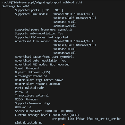
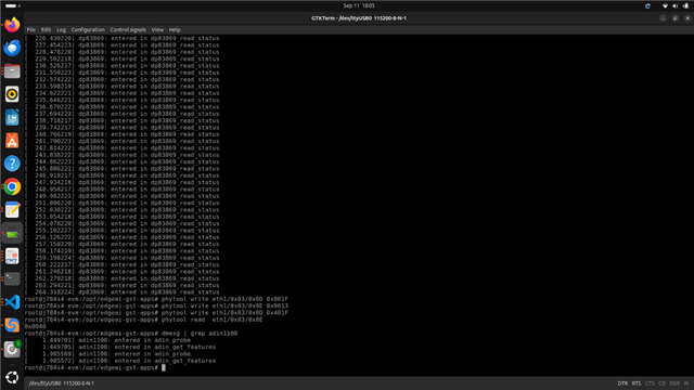
Currently the link is not coming up on the ADIN1100 side
Thanks,
Apuroop Kumar.