DP83826I: Pull-up resistors and capacitors on differential lines

Part Number: DP83826I

Tool/software:

I will be using 100Base, full duplex.

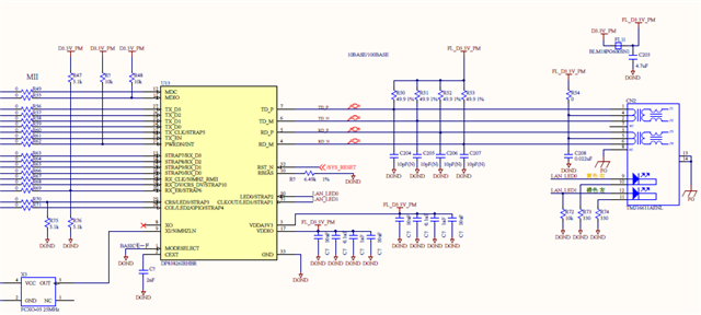
With an IC with the same specs as the DP83826I I was using previously, TD+, TD-, RD+, and RD- were pulled up with 49.9 Ω as shown in the diagram below.

Is this unnecessary with this IC? Also, is the 10pF multilayer ceramic capacitor (not installed) on the same communication line unnecessary?

  • I solved it myself. The old IC was in current drive mode and required a pull-up resistor. This IC is in voltage drive mode, so the circuit around the connector was different.

    By the way, can I use the TMJ16611AENL connector with the DP83826I?
    Since the current circuit is for current drive, I'll need to change the connector peripheral circuit to match the D83826EVM.
    The TMJ16611AENL datasheet can be found at the link below.

    www.taoglas.com/.../TMJ16611AENL.pdf

  • Hi, 

    Your understanding on the current mode driver is correct. DP83826 is voltage mode driver so pull up resistors are not needed. 
    For transformer, we typically recommend turn ratio with +-2% but this is +-3%. This is tolerable, but please note that this may impact the performance. 
    Otherwise, our specifications fit our recommendation. 

    Best,
    J

  • Thank you. I will use this connector. This is another question,

    For surge protection, I've shorted the DGND and FG on the board. Is it okay to insulate the RJ-45 FG (hereafter referred to as FG_LAN) from the board's FG as shown below?

    FG - DGND ... 0Ω

    FG_LAN - DGND&FG ... 1MΩ (Resistor)

  • We typically recommend DGND and earth GND (FG) to be connected with 1Mohm resistor and 4700pF capacitor.

    If you are worried about surge protection, there also is an option to include ESD diodes on the MDI line.

    Best,

    J