This thread has been locked.

If you have a related question, please click the "Ask a related question" button in the top right corner. The newly created question will be automatically linked to this question.

SN75LVPE5412: SN75LVPE5421

Part Number: SN75LVPE5412
Other Parts Discussed in Thread: SN75LVPE5421, DS320PR410, SN74LVC1G04

Tool/software:

Hi Team,

We use SN75LVPE5412&SN75LVPE5421 to design a Gen5 PCIe X4  AIC for MCIO 38P. 


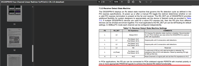
Unlike DS320PR410, there is no similar description in SN75LVPE5412 datasheet. What's the recommended connection of  PD pin  if  we use SN75LVPE5412&SN75LVPE5421? Thank you.

  • Hi Ian,

    See our E2E FAQ for advice on how to configure the PD pin:  [FAQ] DS320PR810: How should PCIe redriver PD pins be configured? 

    Best,

    Evan Su

  • Hi Evan,

    Thanks for your reply, I have another question.

    If  the application is a M.2 M-key to MCIO 4i PCIe 5.0 adapter, Do you still recommend connecting the PD pin through an inverter to the PERST# signal on the M.2 side?

  • Hi Ian,

    If  the application is a M.2 M-key to MCIO 4i PCIe 5.0 adapter, which is not a PCIe application

    I don't quite understand how this is not a PCIe application from what you have described? Adapters will change the routing of the signal lines to fit from the M.2 interface to the MCIO cable interface, but the data being transferred should still be PCIe protocol. PERST# is a PCIe signal, so in a true non-PCIe use case I don't think it would even exist.

    Best,

    Evan Su

  • Hi Evan,

    Thanks for clarifying, this application is indeed a PCIe use case.

    Just to confirm, for this adapter design with a PCIe redriver, is it recommended to connect the PD pin through an inverter to the PERST# signal on the M.2 side?

    Best,
    Ian

  • Hi Ian,

    I would recommend connecting PD to inverted PERST# based on experience. However the PERST# signal is generated by the root complex (probably CPU in this case), so I am not sure what is meant by "on the M.2 side". The M.2 SSD should have a PERST# input to participate in the PCIe link but the signal should pass through the adapter card (where the redriver is) before it gets to the SSD.

    Best,

    Evan Su

  • Hi Evan,

    Thank you  for your explanation regarding the PD connection to inverted PERST#.

    We have implemented the inverter circuit for PERST# in our schematic, and I would appreciate it if you could kindly take a look and confirm whether it is correct.

    Thanks again for your support.

    Best,

    Ian

  • Hi Ian,

    I have not used this inverter before, but judging from the SN74LVC1G04 datasheet it should be OK as long as R112 and R113 are not installed in normal operation. I am not sure about the purpose of R112 however.

    Best,

    Evan Su

  • Hi Evan,

    Regarding the two resistors:

    • R112  is  to provide a defined high level at the inverter input during early power-up when PERST# may be Hi-Z, preventing the input from floating.
    • R113 is a DNP placeholder for evaluation.

    From your perspective, is R112 acceptable here?  Thank you.

    Best,

    Ian

  • Hi Ian,

    I have not seen pull-ups applied to the inverter input in the redriver applications I have seen before, so my thinking is that it's not necessary. During PCIe startup and operation, PERST# is either logic low or logic high, and I am not sure if there is any specified Hi-Z state. But if you think R112 may help then there is probably no harm from including it, it can be removed easily.

    Best,

    Evan Su