Part Number: DP83869HM
Other Parts Discussed in Thread: DP83869
Tool/software:
To whom it may concern -
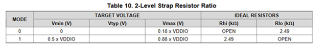
Noticed that the DP83869 Datasheet Revision from C to D, updated the "4-Level Strapping Mode 0 Rlo recommendation changed from 2.49k to OPEN". I assume this is referring to Table 10 2-Level Strap Resistor Ratio instead of the 4-level Strap, because Mode 0 Rlo is changed from 2.49k to OPEN.
Revision C:
Revision D:
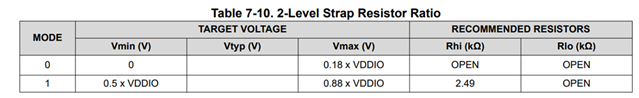
With this in mind, we followed datasheet revision C (with Rlo = 2.49k for 2-level application). Few questions:
- What is the reason for this strap resistor change?
- Do you recommend we do no install the Rlo to align with Revision D?
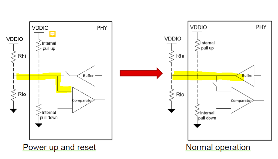
- Since JTAG_TDO is a multi-use pin, how should we strap it if we plan to use JTAG boundary scan?
Thanks,
Brendan