TDP1204: I2C mode work abnormal

Part Number: TDP1204

Tool/software:

Hi Ti team

We are currently using the TDP1204I at the HDMI source end and have encountered the following issue:

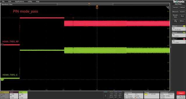
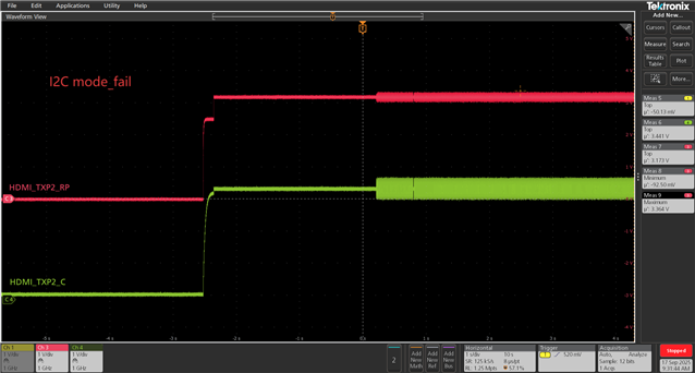
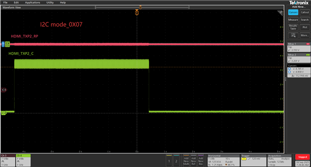
HDMI output functions normally when configured to PIN mode, but fails to work properly when configured to I2C mode.

We have measured that the EN/HPD signals are normal and the DDC channel is functional.

The I2C configuration is shown in the figure below; please help us analysis this issue:

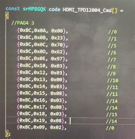
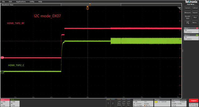
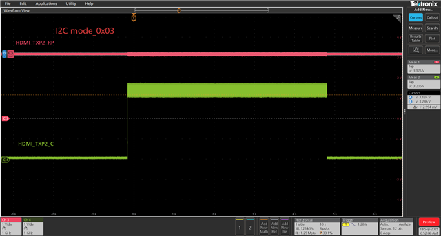
We tried changing EQ gain 08 to 0F and set the 09 register to 00, but there was no improvement.

The attachment contains the DDC logs captured in I2C mode and PIN mode from HDMI connector.

PIN MODE.xlsxI2C MODE.xlsx


PIN MODE.xlsx

  • Hi,

    Is the issue not able to write to the TDP1204 registers? TDP1204 uses 7-bit address, have you tried address 0x5E?

    Thanks

    David

  • Hi 

    TDP1204I registers seems write successful,after write,we read the register address find the data is same as written。

    we use 8-bit address 0xBC/BD(W/R),it same as 7-bit address 0x5E

  • Hi,

    Can you please share your schematic?

    If you write 0x06 to register 0x09 to force TDP1204 into always active mode, are you able to get an output?

    Thanks

    David

  • Hi,

    Follows is schematic,please check

     ‘write 0x06 to register 0x09’ still no improvement 

    TDP1204I.pdf

  • Hi,

    Are you able to see the output waveform in the I2C mode? The register write value looks correct, so I am expecting that you will see the waveform at the TDP1204. If you change the value at register 0x12, 0x14, 0x16, and 0x18 bits [2:0], you should see on the scope the signal amplitude changes as bits [2:0] controls the output SWING, this will tell you that you have full control of the TDP1204 I2C bus.

    Thanks

    David

  • we captured the pass(PIN MODE) and fail(I2C MODE) waveforms,it seems highspeed link is off in I2C MODE,output level is 3.3V always;

    test point: pin.9 & pin.40

    the communication above have DDC log, it look normal or not? 


  • Hi,

    The DDC log looks ok as the source is correctly reading the EDID infomation from the monitor in both pin strap and I2C mode, so the DDC buffer is not the issue here.

    But looking at the waveform, you do have a signal at HDMI_TXP2_RP but the amplitude is very small. 

    If you zoom in to 100mV/div on channel 3. and write a value of 0x04, 05, 06, or 07 to register 0x18, do you see the amplitude increases as you write 0x04 -> 0x05 -> 0x06 -> 0x07 to register 0x18?

    Thanks

    David

  • Hi 

    looking at 0x03&0x07 in register 0x18 waveforms,the ouput HDMI_TXP2_RP is no change,always 3.3V.

    from picture2、3,the samll amplitude variation possible caused by probe crosstalk,instead of output amplitude

    (picture2、3:after entry OS,keep monitor pin.40 HDMI_TXP2_RP,discontinue monitor pin.9 HDMI_TXP2_C, HDMI_TXP2_RP have small amplitude when probe monitor HDMI_TXP2_C)

  • Hi 

    from SPEC,register 0x11 value=5F(reset),but we read the register find actual value=00,we make register 0x11 set to 0F,HDMI I2C mode work normal

    we are worry about whether similar situations might exist in other registers as well(actual reset value not match SPEC reset value)

    could you give me some suggestions