TMDS1204EVM: Configuration Validation for Variable Cable Input to Static HDMI RX Channel

Part Number: TMDS1204EVM
Other Parts Discussed in Thread: TMDS1204, TDP1204

Tool/software:

Hello All,

We are implementing a validation setup using the TMDS1204 and need confirmation on the optimal configuration for our specific use case.

Our Setup:

  • Variable input to TMDS1204 (different cable attachments with varying loss characteristics)

  • Static channel from TMDS1204 TX to our HDMI RX (fixed, known channel characteristics)

  • Need to validate across multiple cable configurations while maintaining consistent TX performance

Our Proposed Configuration:
Based on our analysis of the datasheet and validation requirements, we believe the correct approach is:

  • TMDS1204 RX Side: "Link Training Compatible RX EQ mode" to adaptively handle variable cable loss

  • TMDS1204 TX Side: "Limited mode" with static EQ/output settings for the consistent TX-to-RX channel

Specific Questions:

  • Is "Link Training Compatible RX EQ mode" the correct feature for handling variable input cable characteristics? We want the RX side to adapt to different cable losses (different attach scenarios) while keeping TX settings optimized for our known post-channel.

  • Configuration registers: What's the proper I2C register configuration to enable this adaptive RX mode? We see references to:

    • AEQEN register for adaptive EQ

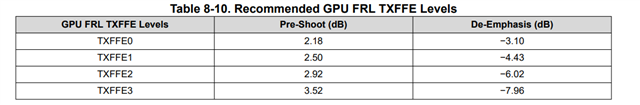
    • Table 7-11 Link Training Compatible RX EQ Adjustments

    • MODE pin settings for enabling AEQ functionality

  • Limited vs Linear mode confirmation: For our static TX channel (TMDS1204 to HDMI RX), limited mode should provide consistent, HDMI-compliant output levels regardless of input variations - correct?

  • DDC snooping: Should we disable DDC snooping (register 0A = 05h) since we're doing characterization testing rather than normal HDMI negotiation?

Thanks in advance!

  • Hi,

    Please see this app note on how to use the TMDS1204 adaptive equalization. It includes I2C script to configure TMDS1204 for the AEQ feature. 

    You should use limited mode as it decouples the TMDS1204 TX from its RX. 

    How do you implement the DDC bus in your design? Are you providing any snooping capability? Some function, such as TX termination control, the default is depending on the snooping, so you may have to manually set the control if snooping is disabled.

    Thanks
    David

  • Hey David,

    Thanks for the SNLA419 reference - very helpful for understanding AEQ implementation.

    I have a specific setup question regarding single lane BERT testing with the TMDS1204 EVM:

    My Setup:

    • BERT Pattern Generator → TMDS1204 EVM → Scope
    • Single lane only (i.e. CLK lane, register 11h = 08h)
    • PRBS-15 at 2.97 Gbps for signal integrity validation
    • Testing variable input conditions (cable lengths, signal levels)

    Questions:

    AEQ Single Lane Compatibility: Any constraints using Adaptive EQ with only one lane enabled? Does AEQ need multiple active lanes or can it adapt effectively on single lane basis?

    Manual vs Auto EQ for BERT: For single-lane BERT, is it better to use Auto EQ for varying conditions or manual/fixed EQ for repeatable measurements?

    Manual EQ Optimization: If going manual route, what's recommended method to determine optimal EQ settings? Start with pin-strap EQ settings and iterate? Use eye diagram analysis at the output?

    DDC Relevance: In BERT-to-scope setup (no actual HDMI display), is DDC snooping relevant? Currently disabling it (0A = 05h) since no HDMI negotiation occurs.

    Any experience with TMDS1204 BERT testing, particularly AEQ behavior with single lanes and best practices for EQ config in measurement setups?

    Thanks!

  • Hi,

    For this particular test, I would recommend using TMD1204 I2C mode as you can make setting change on the fly without power cycling the TMDS1204. 

    The adaption will only occur during the TXFFE0 portion of FRL link training when LTP5, LTP6, LTP7, or LTP8 is being received. So you have to create a LTP5, 6, 7, or 8 data pattern with the Bert. 

    DDC is not relevant if you are using a Bert, but you will have to manually configure TMDS1204 into FRL mode. This is done by writing a non-0 value to register 0x31 bit[3:0].

    The AEQ operates only on IN_D0 pins (pins 12 and 13). The EQ value determined by AEQ will be applied to the other FRL data lanes. So for single lane, you can't use CLK lane, you have to use lane 0. 

    Once the AEQ is completed, you can read register 0x50 bit[3-0] for adapted EQ value and register 0x51 bit[3-0] for Eye stat value, 0x51 bit[6-4] for VOD range stat value.

    You can use a sampling scope to measure the eye width and eye height at the TMDS1204 and plot it against the input channel insertion loss, source TX setting.

    Thanks

    David

  • Thanks David that was helpful. I had a few additional queries on some other things.

    Could you please clarify the minimum and maximum end-to-end channel insertion loss supported by the TMDS1204 on both RX and TX sides? From the datasheet, I see up to 12dB RX EQ at 6GHz, but I'd like confirmation of:

    • Maximum and minimum supported pre-channel loss (source-to-TMDS1204)
    • Maximum and minimum supported post-channel loss (TMDS1204-to-sink)
    • Any specific loss profile requirements or limitations

    For our application using limited redriver mode with cable/loss variation, what is the correct I²C configuration sequence to enable adaptive EQ? Specifically:

    • Required register settings for AEQ in limited mode
    • Proper FRL mode entry sequence for AEQ operation
    • Whether manual TXFFE control (0x0A[1:0]=01) is compatible with AEQ

    Regarding FRL link training support, I want to confirm my understanding:

    • Is link training support available for both RX and TX sides of the TMDS1204?
    • Does Linear mode adjust TX EQ with respect to auto RX EQ convergence?
    • Does Limited mode converge auto RX EQ but does not change TX EQ?
  • Hi,

    Please see my inserted response below.

    • Maximum and minimum supported pre-channel loss (source-to-TMDS1204)
      • Please refer to Section 8.2 and Table 8-2 for the supported channel loss on the source side
    • Maximum and minimum supported post-channel loss (TMDS1204-to-sink)
      • Please refer to Section 8-3 and Table 8-6 for the supported channel loss on the sink side
    • Any specific loss profile requirements or limitations
      • No

    Before we dive deeper, I want to clarify something quick. The TMDS1204 supports both Adaptive EQ (AEQ) and Link Training Compatible Rx EQ. Which mode do you want to implement?

    Thanks

    David

  • Hey David,

    We are looking to use the Link Training Compatible Rx EQ mode. Our use case involves compensating for channel/cable loss variation using adaptive equalization at the RX input (specifically, during HDMI2.1 FRL link training), with the TX output set to limited (static) mode for compliance and consistent downstream signal quality. Hope that clears up what we're trying to accomplish. 

  • Hi,

    The Link Training Compatible Rx EQ mode is recommended in source application. Below is the TXFFE levels that this mode assumes the GPU is using. Can this requirement be supported by your source?

    In your case, which you are trying to have adaptive equalization at the RX input to different channel/cable loss, this is more a sink application. In which case, you would want to use the TMDS1204  Adaptive EQ (AEQ) feature and put the TDP1204 into linear re-driver.

    Please correct me if my understanding is not correct.

    Thanks

    David

  • Hey David,

    So We’ve confirmed our system requires Limited Mode on the TX side—because we have a static TMDS1204 TX-to-RX channel and need consistent output for BERT measurements. Simultaneously, we need adaptive RX equalization at the TMDS1204 input to handle varying cable loss scenarios across different test fixtures.

    Could you also clarify whether in Linear Mode the TMDS1204 TX EQ tracks the RX EQ convergence, and in Limited Mode the TX EQ remains fixed despite RX adaptation. We would also like clarification on if the difference between Linear and Limited modes is just that the TX changes with adaptation or it does not. 

  • Hi,

    When TMDS1204 is in the linear mode, it does not have any TX control. So the output signal is almost a linear function of the input signal as long as the input signal is within the TMDS1204 input linearity range.

    When TMDS1204 is in the limited mode, then the TX is decoupled completely from the RX. TX output can be remain fixed by setting TXFFE_SNOOP_CTRL bit in register 0xA to a value of 0x02(DDC snooping disabled), and TXFFE can then controlled through writes to CLK_TXFFE, D0_TXFFE, D1_TXFFE, and D2_TXFFE.

    Thanks

    David

  • Hey David,

    Just had a few questions to clarify on some things regarding our validation setup.

    For the supported reaches, mentioned in Tables 8‑2 and 8‑6, if I'm understanding correctly these values shouldn't change based on limited and linear mode correct?

    Does the TMDS1204 allow static TX pre-emphasis/de-emphasis to be configured when HDMI 2.1 FRL is enabled in limited mode so we can tune a static channel or is that only not available in linear mode?

  • Hi,

    For the supported reaches, mentioned in Tables 8‑2 and 8‑6, if I'm understanding correctly these values shouldn't change based on limited and linear mode correct?

    Correct. these values do not change. In linear mode, the TMDS1204 RX EQ can compensate the pre-channel and a little bit of post-channel. In limited mode, the RX EQ compensate the pre-channel and the TX EQ compensate the post-channel. 

    Does the TMDS1204 allow static TX pre-emphasis/de-emphasis to be configured when HDMI 2.1 FRL is enabled in limited mode so we can tune a static channel or is that only not available in linear mode?

    TX output is only available in limited mode and can be remain fixed by setting TXFFE_SNOOP_CTRL bit in register 0xA to a value of 0x02(DDC snooping disabled), and TXFFE can then controlled through writes to CLK_TXFFE, D0_TXFFE, D1_TXFFE, and D2_TXFFE.

    Thanks

    David

  • Thanks for all of the information so far David, you've been very helpful with piecing this all together.
    I did have one other question regarding the proper BERT sequence to trigger AEQ.

    For context we’re driving TMDS1204 with a BERT acting as the HDMI 2.1 FRL source and need TI’s recommended minimal sequence to ensure the device’s AEQ runs and converges before TX measurements, without a full HDMI GPU in the loop. 

    What exact FRL training patterns and order (e.g., LTP5–LTP8) and minimum dwell time at TXFFE0 are required so AEQ completes, and are BERT‑generated equivalents acceptable if full FRL framing isn’t present?

  • Hi,

    The TMDS1204 will perform adaptive equalization when FRL link training begins. It will also re-adapt each time the data rate changes. The adaption will only occur during the TXFFE0 portion of FRL link training when LTP5, LTP6, LTP7, or LTP8 is being received. So for the Bert, you will want it to output one of the LTP link training pattern.

    Also the AEQ is only supported in HDMI2.1 mode. So you want to make sure the register 0x31 is set to the "Not 0h".

    The time from start of FRL link training to AEQ complete for 6Gbps, 8Gbps, 10Gbps, and 12Gbps is max of 0.5ms. You can also poll AEQ_STATUS Register (Offset = 50h) bit 7 to make sure AEQ is completed.

    Thanks

    David